Advertisement
Quick Links
QUICK INSTALLATION GUIDE
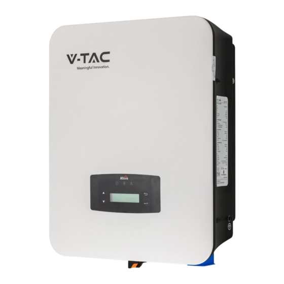
OVERVIEW
DC Connectors ( + ) For PV Strings
DC Switch
Battery Port
PACKAGE LIST
1
2
3
Certificate
Installation
Of Inspection
Instructions
7
8
5 14
5 15
16
13
IN C
N
R
R
DEALERS. V-TAC EUROPE LTD. Karavelow 9B, bul.L, Plovdiv 4000, Bulgaria
4
5
5
6
Monitoring
Quick
Warranty
Quick
Card
Installation
Instructions
9
11
12
10
17
19
18
User Manual QR CODE
Please scan the QR code to access the manual
in multiple languages.
WITH
R
CTS RANG , INQUIR
No. Qty
Items
1
1
Hybrid Inverter
1
2
Certificate Of Inspection
1
3
Quick Installation Instructions
4
1
Warranty Card
1
5
Monitoring Quick Installation Instructions
1
6
CT
7
1
Battery wire
8
1
Security Screw
3
Communication Connectors
9
1
Wall Mounting Bracket
10
CT
A
C
TAC
Communication Port
AC Port & EPS Port
Monitor Module Port
No. Qty
Items
11
1
Battery Connector
1
12
Monitor Module
2
13
DC Connector
14
3
Mounting Bracket Screw
3
15
Plastic Expansion Tube
1
16
Smart Meter (Opitional)
17
1
AC Waterproof Cover
18
1
Meter Conncetors
Communication T568B
2
19
T
AT
RT@V-TA
T
Advertisement

Subscribe to Our Youtube Channel
Related Manuals for V-TAC Afore VT-AF6K-SLP


Summary of Contents for V-TAC Afore VT-AF6K-SLP
- Page 1 Communication T568B Communication Connectors Wall Mounting Bracket User Manual QR CODE Please scan the QR code to access the manual in multiple languages. IN C WITH RT@V-TA CTS RANG , INQUIR DEALERS. V-TAC EUROPE LTD. Karavelow 9B, bul.L, Plovdiv 4000, Bulgaria...
- Page 2 MOUNTING Security 219mm screw 17mm 264mm PV CONNECTION Note: 4mm² Warning: Note: Note: BATTERY CONNECTION Rotate counterclockwise and remove mounting bracket Pass the battery wire with the correct polarity through the nut screw nut. and installation bracket. Note: Battery cable suggestion Cross-section 4 AWG.
- Page 3 12345678 12345678 T568B T568B Assignment Assignment CANH_BAT1 BAT-485-A BAT-485-B CANL_BAT1 P i n8 765 432 1 P i n1 234 546 78 BAT-485 CAN-485 CAN/RS485 Lithium GRID AND EPS CONNETION Note: Cable suggestion Cross-section 8-10AWG. Note: The Max. power load connects to EPS port should not 10±0.5mm exceed the inverter's EPS Max.
- Page 4 CT OR METER CONNETION Grid Main Breaker CT or Meter Meter Load CT Port pin assignment Meter Port pin assignment Assignment Assignment Smart Meter CT-U RS485 A CT-N RS485 B Meter Note: 24 25 Please follow below pin order RS485A to single-phase meter (Pin 24) RS485B to single-phase meter (Pin 25) WIFI CONNECTION Wifi/GPRS...
Need help?
Do you have a question about the Afore VT-AF6K-SLP and is the answer not in the manual?
Questions and answers