Table of Contents
Advertisement
Quick Links
MODEL
VT-6607136
SKU
11576
PV INPUT PARAMETER
Mppt Input Voltage
Vmax PV
Max. Input Current
lsc PV
AC INOUT/OUTOUT PARAMETER
Rated Apparent Power
Rated Current
Rated Voltage
Rated Frequency
Power Factor Range
BATTERY PARAMETER
Storage type:
Battery input voltage:
Cut Off Voltage:
Max. charging Voltage:
Max. Protective Voltage:
Max. continuous charging
Current:
Max.Discharging Current:
Thank you for selecting and buying V-TAC product. V-TAC will serve you the best. Please read these instruc-
tions carefully before starting the installation and keep this manual handy for future reference. If you have any
another query, please contact our dealer or local vendor from whom you have purchased the product. They
are trained and ready to serve you at the best. The warranty is valid for 5 years from the date of purchase. The
warranty does not apply to damage caused by incorrect installation or abnormal wear and tear. The company
gives no warranty against damage to any surface due to incorrect removal and installation of the product.
This product is warranted for manufacturing defects only.
IN CASE OF ANY QUERY/ISSUE WITH THE PRODUCT, PLEASE REACH OUT TO US AT: SUPPORT@V-TAC.EU
FOR MORE PRODUCTS RANGE, INQUIRY PLEASE CONTACT OUR DISTRIBUTOR OR NEAREST
DEALERS. V-TAC EUROPE LTD. BULGARIA, PLOVDIV 4000, BUL.L.KARAVELOW 9B
INSTRUCTION MANUAL
HYBRID SOLAR INVERTER
550V
550V
18.5x2A
26x2A
3.6kVA
16.4/15.7A
198 to
242@220/207 to
253@230V
50/60Hz
1 (-0.8~+0.8 adjust-
able)
Li-ion / Lead-acid
etc.
Protective Class:
40V-60V
Type of Isolation:
39.5V
Ingress Protection:
60V
Over Voltage Category:
62V
Dimension(W*D*H):
80A
Weight:
80A
Max.Efficiency:
INTRODUCTION
MULTI-LANGUAGE MANUAL QR CODE
Please scan the QR code to access the manual in
multiple languages.
SYSTEM
Class I
Transformerless
IP65
II
513*370*192mm
17kg
97.6%
WEEE Number: 80133970
Advertisement
Table of Contents
Troubleshooting

Related Manuals for V-TAC VT-6607136


Summary of Contents for V-TAC VT-6607136
- Page 1 97.6% INTRODUCTION Thank you for selecting and buying V-TAC product. V-TAC will serve you the best. Please read these instruc- tions carefully before starting the installation and keep this manual handy for future reference. If you have any another query, please contact our dealer or local vendor from whom you have purchased the product. They are trained and ready to serve you at the best.
-
Page 2: Safety Precautions
WARNING 1. Please make sure to turn off the power before starting the installation. 2. Installation must be performed by a qualified electrician. SAFETY PRECAUTIONS inverter must be carried out by qualified electricians. 1. All work on the 2. The PV panels and inverter must be connected to the ground. 3. -
Page 3: Basic Instruction
INTRODUCTION Basic Instruction The VTAC hybrid inverters are designed to increase energy independence for homeowners. Energy manag ment is based on time-of-use and demand charge rate structures, significantly reduce the amount of energy purchased from the public grid and optimize self-consumption. Hybrid Inverter PV Array Meter... -
Page 4: Time Of Use
Time of Use The Time of Use mode is designed to reward customers who do their part to reduce demand on the electric grid, particularly during peak usage periods. Use most of your electricity from PV energy and during off-peak time periods, and you could significantly lower your monthly bill. A. - Page 5 C. Forbidden Discharge 4 periods of time discharge setting, the battery will be charged firstly. Energy flow: PV → Battery → Load → Grid Selling First The Selling First mode is suitable for the regions with high feed-in tariff. Energy flow: PV →...
-
Page 6: Installation
INSTALLATION Pre-installation Unpacking & Package List Unpacking On receiving the inverter, please check to make sure the packing and all components are not miss- ing or damaged. Please contact your dealer directly for supports if there is any damage or missing components. -
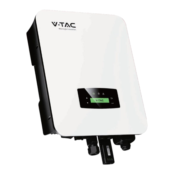
Page 7: Product Overview
Product Overview Inverter Terminals Items Items DC Switch Communication Port DC Connectors ( + ) For PV Strings AC Port & EPS Port DC Connectors ( − ) For PV Strings Monitor Module Port Battery Port... -
Page 8: Mounting Location
Mounting Location The inverters are designed for indoor and outdoor installation (IP65), to increase the safety, perfo mance and lifespan of the inverter, please select the mounting location carefully based on the fol- lowing rules: • The inverter should be installed on a solid surface, far from flammable or corrosion materials, where is suitable for inverter’s weight and dimensions. - Page 9 • Leave the enough space around inverter, easy for accessing to the inverter, connection points and maintenance. Mounting STEP 1 STEP 2...
-
Page 10: Electrical Connection
STEP 3 Electrical Connection Communication Adapter pin assignment COM1 COM2 NTC+ Meter 485A NTC- Meter 485B Dry Contact BAT 485A Dry Contact BAT CANH BAT CANL BAT 485B 485A 485B Note: For diesel generators or multi-machine parallel use, please contact the manufacturer, and provide installation and operation instructions separately. - Page 11 PV Connection The hybrid inverter has two MPPT channels, can be connected with two strings of PV panels. Please make sure below requirements are followed before connecting PV panels and strings to the inverter: • The open-circuit voltage and short-circuit current of PV string should not exceed the reasonable range of the inverters.
- Page 12 STEP 3 Battery Connection Hybrid inverters are compatible with lithium battery. For lead acid battery or batteries with other brands, please confirm with local distributor or VTAC for technical support. Note: Set battery type and manufacturer, please refer to Chapter 5.3. BMS(Battery Management System)communication is needed between inverter and battery.
- Page 13 STEP 3 Insert the wire harness into the terminals according to “+” and “-” polarity, make the insulated ter- minals parallel with the terminals , the crimping screw torque is 2.0±0.1N.m STEP 4 A “click” sound will be heard when the connector assembly is correct. STEP 5 Use an open-end wrench to tighten the waterproof lock.
- Page 14 BAT-CAN/RS485 BAT-NTC...
- Page 15 Multi Inverter Parallel...
- Page 16 An extra AC breaker is needed for On-Grid connection to be isolated from grid when necessary. Below are requirements for the On-Grid AC-breaker. Inverter Model AC breaker specification VT-6607136 63A/200V/230V AC breaker Note: Qualified electrician will be required for the wiring.
- Page 17 STEP 2 GRID EPS Load STEP 3 Fix the AC wiring cover with cover screws GRID EPS Load...
- Page 18 CT or Meter Connection Meter and a current sensor(CT for short below) are used to detect current power direction of the local load and the grid. The output control function of the inverters will be activated based on the detected data. Install the CT...
-
Page 19: Communication Connection
Install the Meter Communication Connection The monitoring module could transmit the data to the cloud server, and display the data on the PC, tablet and smart-phone. Install the WIFI / Ethernet / GPRS / RS485 Communication WIFI / Ethernet / GPRS / RS485 communication is applicable to the inverter. Please refer to “Communication Configuration Instruction”... - Page 20 STEP 2 Turn on the DC switch and AC circuit breaker, and wait until the LED indicator on the monitoring module flashes, indicating that the monitoring module is successfully connected. Earth Connection Note: A second protective earth (PE) terminal should be connected to the inverter. This prevents electric shock if the original protective PE wire fails.
-
Page 21: Operation
STEP 2 Fix the grounding screw to the grounding connection of the machine housing. Note: Make sure the earth cables on the inverter and solar panel frame are separately. Operation Control Panel Items Items LCD Display UP Touch Button POWER LED Indicator DOWN Touch Button GRID LED Indicator BACK Touch Button... -
Page 22: Menu Overview
Note: Hold UP/DOWN button can be rolling quickly. SIGN POWER COLOR EXPLANATION Green The inverter is stand-by POWER The inverter is power off Green The inverter is feeding power GRID The inverter is not feeding power Fault occurred FAULT No fault Menu Overview 3.6kW hybrid inverter has a LCD for clearly operating, and menu of the LCD can be presented as following:... -
Page 23: Inverter Setting
Inverter Setting The setting is for 3.6kW Hybrid inverter. Any doubts, please contact distributor for more details. Time & Date System parameters setting System parameters setting Safety Specifications Note: Select the safty according to the requirements of the installation site. -
Page 24: Lithium Battery
Lithium Battery Operating parameters setting 5 4 3 2 Note: Please select the right battery frand to your use. PV Mode Operating parameters setting 5 4 3 2 1. No PV connection 2. “Independent” and “Parallel” setting for professional installers. - Page 25 Lead Acid Operating parameters setting 5 4 3 2 Capacity range (0~1000Ah) Energy Management System (EMS Param) Operating parameters setting 5 4 3 2 Energy management system parameters setting 1. Self-Use 2. Back-Up 3. Selling First 4. Maintain (In development) 5.
- Page 26 Time of Use Operating parameters setting 5 4 3 2 Energy management system parameters setting Charge / discharge. Charge / discharge power range -10000W~10000W. Battery charge / discharge setting. 1. Upper state of charge. 2. Lower state of charge. 3. Battery Overvoltage Threshold. 4.
- Page 27 AC Charging Operating parameters setting 5 4 3 2 Energy management system parameters setting AC charging 1. ACChg — AC charging enable. 2. MaxPpct — AC charging Percentage. 3. MaxSoc — AC charging maximum Soc. 4. TimOff1 — AC charging start time1. 5.
-
Page 28: Protection Parameters
Forced Discharging Operating parameters setting 5 4 3 2 Energy management system parameters setting Forced discharge 1. ForceDChg — Forced discharging enable. 2. PForce — Forced discharging power percentage. 3. MinSoc — Forced discharging max Soc. 4. TimOn1 — Forced discharging start time 1. 5. - Page 29 Multi-machine in Parallel Communication parameters setting 1. Address 2. Band rate 3. Parallel enable 1. Inverter parallel amount 2. Master / Slave 3. Address of slave 4. Only slave can choose address. Diesel Generator Setting (Diese1 Gen Param) Operating parameters setting 5 4 3 2 Diesel generator parameters 1.
-
Page 30: Power On/Off
POWER ON/OFF Please check the following requirements before testing: • Installation location is suitable according to Chapter 4.1.3. • All electrical wires are connected tightly, including PV modules, battery and AC side(Such as the grid side, EPS side, Gen side). •... -
Page 31: Fault Code And Trouble Shooting
Fault Code and Trouble Shooting TYPE OF CODE NAME DESCRIPTION RECOMMEND SOLUTION FAULT • Check PV modules con- PV connection type nection PvConnectFault different from setup • Check PV Mode setup Ref. Chapter 5.3. • Check PV modules wires, those wires are soaked or damaged, and then carry ISO check among out rectification. - Page 32 TYPE OF CODE NAME DESCRIPTION RECOMMEND SOLUTION FAULT PV9ReverseFault PV10ReverseFault PV11ReverseFault PV12ReverseFault Pv1AbnormalFault Pv2AbnormalFault Pv3AbnormalFault Pv4AbnormalFault Pv5AbnormalFault Pv6AbnormalFault Pv7AbnormalFault Pv8AbnormalFault Pv9AbnormalFault Pv10AbnormalFault PV FAULT Pv11AbnormalFault • Check PV modules partial occlusion or cells damaged. Pv12AbnormalFault PV(+) and PV(-) • Check PV module wires reversed Connection Pv13AbnormalFault and connectors broken or...
- Page 33 TYPE OF CODE NAME DESCRIPTION RECOMMEND SOLUTION FAULT • Check Bat.(+) and Bat.(-) connect PcsBatReversed- Bat. (+) and Bat. (-) reversed or not. Fault are reversed. • Make correction If re- versed. • Check battery wires and connectors damage or loose PcsBatConnect- Battery wires loose connect.
- Page 34 TYPE OF CODE NAME DESCRIPTION RECOMMEND SOLUTION FAULT CelTemperature- OverFa CelTemperatureUn- derF BatIsoFault BatSocLowFault BmsInterComFault BatRelayFault BatPreChaFault BmsBatChgMos- Fault BmsBatDChgMos- Fault BMSVolOVFault BMSVolLFault VolLockOpenFault VolLockShortFault Battery ChgRefOVFault Fault • Inverter will restart au- tomatically when the grid return to normal. GridLossFault Grid lost (islanding) •...
- Page 35 TYPE OF CODE NAME DESCRIPTION RECOMMEND SOLUTION FAULT • The inverter will restart automatically when the grid three phase return to normal. Grid10MinOverVolt- Grid voltage Over by • Contact with local distrib- Fault 10 Minutes utor or required grid company ad- just 10 minutes protection voltage parame- ters.
- Page 36 TYPE OF CODE NAME DESCRIPTION RECOMMEND SOLUTION FAULT Pv1HwOverCurrFault Pv2HwOverCurrFault Pv3HwOverCurrFault Pv4HwOverCurrFault Pv5HwOverCurrFault • Power off, then restart (Ref. Pv6HwOverCurrFault Chapter8). PV current over, trig- • If those faults occurs Pv7HwOverCurrFault gered by hardware continuously and frequent- protection circuit Pv8HwOverCurrFault ly, please ask help for local distributors.
- Page 37 TYPE OF CODE NAME DESCRIPTION RECOMMEND SOLUTION FAULT Boost7SelfCheck(- boost)Fault Boost8SelfCheck(- boost)Fault Boost9SelfCheck(- boost)Fault Boost10SelfCheck(- boost)Fault Boost11SelfCheck(- boost)Fault Boost12SelfCheck(- boost)Fault BusHwOverVoltFault BusHwOverHalfVolt- Fault Bus voltage over • Power off, then restart (Ref. BusSwOverVoltFault Chapter8). BusSwOverHalfVolt- • If those faults continuously Fault and frequently, please ask Bus voltage under as...
- Page 38 TYPE OF CODE NAME DESCRIPTION RECOMMEND SOLUTION FAULT All over current/ HwOverFault voltage by protection hardware InvHwOverCurr- Ac over current by • Power off, then restart (Ref. Fault protection hardware Chapter8). InvROverCurrFault R phase current over • If those faults occurs InvSOverCurrFault S phase current over continuously and frequent-...
- Page 39 TYPE OF CODE NAME DESCRIPTION RECOMMEND SOLUTION FAULT UpsOverVoltFault Off-grid output volt- • Power off, then restart (Ref. age over or under Chapter8). UpsUnderVoltFault • If those faults occurs con- UpsOverFreqFault Off-grid output fre- AC Fault tinuously and quency over or under UpsUnderFreqFault frequently, please ask help for local...
- Page 40 TYPE OF CODE NAME DESCRIPTION RECOMMEND SOLUTION FAULT GenTCurAdChan- Fault UpsRDcvAdChan- Fault UpsSDcvAdChan- Fault UpsTDcvAdChan- Fault All temperature sen- TempAdChanFault sors abnormal The sample value of VoltAdConflictFault PV, battery and BUS • Power off, then restart (Ref. voltage inconsistent Chapter8). •...
- Page 41 TYPE OF CODE NAME DESCRIPTION RECOMMEND SOLUTION FAULT EnvirTempAdChan- • The warnings are not mat- Warning ter influence. • Power off, then restart (Ref. CoolingTempAd- Some temperature Chapter8). ChanWarning sensors abnormal • If those faults occurs continuously and frequent- Temp3AdChanWarn- ly, please ask help for local distributors.
- Page 42 TYPE OF CODE NAME DESCRIPTION RECOMMEND SOLUTION FAULT • Check earth line connec- tion or earth connecting impedance. • if abnormal, then adjust it. Earth impedance GndAbnormal- • Power off, then restart (Ref. over by Warning Chapter8). cable loose and so on •...
-
Page 43: Specifications
SPECIFICATIONS PV INPUT VT-6607136 Max. Input Power (kW) Max. PV Voltage (V) MPPT Range (V) 80-500 Full MPPT Range (V) 110-500 Normal Voltage (V) Startup Voltage (V) Max. Input Current (A) 18.5X2 Max. Short Current (A) 26X2 No. of MPP Tracker / No. of PV String BATTERY PORT Max. - Page 44 Max. Efficiency (%) 97.6 PV to Bat. Efficiency (%) 98.1 Bat. between AC Efficiency (%) 96.8 PROTECTION VT-6607136 PV Reverse Polarity Protection Over Current/Voltage Protection Anti-Islanding Protection AC Short Circuit Protection Residual Current Detection Ground Fault Monitoring Insulation Resister Detection...
- Page 45 Please scan the QR code to access the manual in multiple languages. IN CASE OF ANY QUERY/ISSUE WITH THE PRODUCT, PLEASE REACH OUT TO US AT: SUPPORT@V-TAC.EU FOR MORE PRODUCTS RANGE, INQUIRY PLEASE CONTACT OUR DISTRIBUTOR OR NEAREST DEALERS. VTAC UK LTD. V-TAC HOUSE, Kelpatrick Road, Slough, London UK, Postcode: SL1 6BW...
-
Page 46: Download App
WARNING 1. Please make sure to turn off the power before starting the installation. 2. Installation must be performed by a qualified electrician. This marking indicates that this Caution, risk of product should not be disposed electric shock. of with other household wastes. NOTICE: Please read this manual carefully before using products and keep it in the place where O&M providers can easily find. -
Page 47: Wifi Module Installation
1. WIFI MODULE INSTALLATION Type 1 Step1: Assemble WIFI Module to the inverter communication interface as shown in the diagram. Warning: Please do not hold the WIFI Module body to rotate while install or remove the Module. 2. WIFI MODULE STATUS Check Indicator light Lights Implication... - Page 48 ABNORMAL STATE PROCESSING If the data on platform is abnormal when the WIFI Module is running, please check the table below and according to the status of indicator lights to complete a simple troubleshooting. If it still can not be resolved or indicator lights status do not show in the table below, please contact Customer Support.
- Page 49 USAGE METHODS AND NOTICES FOR RESET BUTTON Usage methods and key-press descriptions for Reset button Key-press Status Descrip on Light Status Short press 1s SMARTLINK rapid networking status. NET light ashes fast for 100ms. WIFI Module Long press 5s Reboo ng the All lights are ex nguished immediately.
- Page 50 3.Add a Logger Method 1: Enter logger SN manually. Method 2: Click the icon in the right and scan to enter logger SN You can find logger SN in the external packaging or on the logger body. 4.Network Configuration After the logger is added, please configure the network to ensure normal operation.
- Page 51 (5) Shorten the distance between the phone and device. (6) Try to connect to other Wi-Fi. Warning: Please make sure the WIFI Module is working properly before you leave the site. If there is anything abnormal,please do not leave the site and contact customer service: support@v-tac.
-
Page 52: Package List
QUICK INSTALLATION GUIDE OVERVIEW DC Connectors ( + ) For PV Strings Communication Port DC Switch AC Port & EPS Port Battery Port Monitor Module Port PACKAGE LIST No. Qty Items No. Qty Items Hybrid Inverter Monitoring Quick Certificate Warranty Quick Installation Of Inspection... -
Page 53: Battery Connection
MOUNTING s re 219mm 17mm 264mm PV CONNECTION Note: 4mm² Warning: Note: Note: BATTERY CONNECTION 19±1mm Note:... - Page 54 2 3 4 5 6 7 8 6 7 8 Assignment Assignment RS485A CAN/RS485 CANH CANL Lithium CAN-485 BAT-485 GRID AND EPS CONNETION Note: Note: 10±0.5mm Note: GRID EPS Load GRID EPS Load...
-
Page 55: Ground Connection
CT OR METER CONNETION Main Breaker 1 2 3 4 5 6 7 8 4 5 6 7 8 Grid Assignment Assignment Load Meter WIFI CONNECTION Scan code download APP Con gure the Monitor Module, router, account registration, etc. Please check the WiFi connection manual for details.
Need help?
Do you have a question about the VT-6607136 and is the answer not in the manual?
Questions and answers