
Related Manuals for Pickering PXI BRIC 40-569


Summary of Contents for Pickering PXI BRIC 40-569
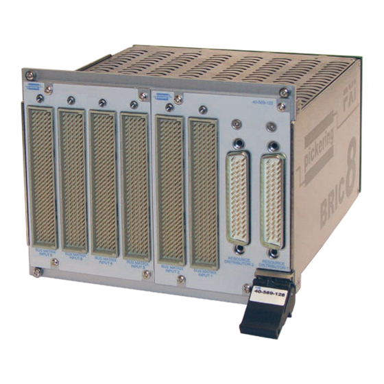
- Page 1 40-569 User Manual PXI BRIC™ Resource Distributor & Bus Matrix Inputs Module pickeringtest.com Issue 3.7 May 2023...
- Page 2 © COPYRIGHT (2023) PICKERING INTERFACES. ALL RIGHTS RESERVED. No part of this publication may be reproduced, transmitted, transcribed, translated or stored in any form, or by any means without the written permission of Pickering Interfaces. Technical details contained within this publication are subject to change without notice.
- Page 3 Pickering Interfaces strives to fulfil all relevant environmental laws and regulations and reduce wastes and releases to the environment. Pickering Interfaces aims to design and operate products in a way that protects the environment and the health and safety of its employees, customers and the public. Pickering Interfaces endeavours to develop and manufacture products that can be produced, distributed, used and recycled, or disposed of, in a safe and environmentally friendly manner.
-
Page 4: Product Safety
PRODUCT SAFETY SAFETY SYMBOLS The following safety symbols may be used on the product and throughout the product documentation. MEANING / DESCRIPTION SYMBOL PROTECTIVE EARTH (GROUND) To identify any terminal which is intended for connection to an external conductor for protection against electric shock in case of a fault, or the terminal of a protective earth (ground) electrode. -
Page 5: Table Of Contents
Pre Operation Checks ............3.1 Hardware Installation ............3.2 Software Installation .............3.2 Testing Operation ..............3.3 Section 4 Programming Guide ..............4.1 Programming Options For Pickering PXI Modules ....4.1 Module Architecture 40-569 ..........4.2 Sub-Units and Programming ..........4.2 Section 5 Connector Information ..............5.1 Section 6 Trouble Shooting .................6.1... - Page 6 THIS PAGE INTENTIONALLY BLANK RESOURCE DISTRIBUTOR & BUS MATRIX INPUTS MODULE 40-569 Page (VI)
-
Page 7: Warnings And Cautions
Not to be used in safety critical circuits, refer to the Pickering Interfaces’ terms & conditions of sale. This module must not be used for the switching of Mains Circuits. For the switching of voltages up to the module’s full specification, Secondary Circuit power supplies and the Device Under Test must... - Page 8 CAUTION - PRODUCT DOCUMENTATION SYMBOL Suitably qualified & trained users should ensure that the accompanying documentation is fully read and understood before attempting to install or operate the product. SAFETY INSTRUCTIONS SAFETY INSTRUCTIONS All cleaning and servicing requires the equipment to be isolated and disconnected from the power source and user I/O signals (refer to the Maintenance Section).
-
Page 9: Technical Specification
Analog busing is housed within the module using a high Typical applications include signal routing for avionics test systems performance screened analog backplane. Pickering can construct that conform to the ARINC 608A specification. The flexibility of custom cable assemblies for all of our PXI modules, please contact the 40-569 BRIC module allows a custom combination of Bus sales office for further assistance. - Page 10 ALL MATRIX CROSSPOINTS 160-PIN DIN 41612 CONNECTOR ARE 4-POLE WITH INDEPENDANT 2-POLE FUNCTIONALITY Schematic Diagram For The Bus Matrix Inputs Daughter Card Pickering PXI Modules are compatible with Mass Interconnect solutions from both VPC and MAC Panel. Shown is the 40-569 with the MAC Panel Scout pickeringtest.com...
- Page 11 • Simpler and faster programming with Direct I/O, VISA and IVI Drivers + LabView Soft Front Panels. • Custom versions built to order. The 40-569 Matrix module is based on the proven features of Pickering’s large range of BRIC Integrated Matrix modules.
- Page 12 Expected Life (operations) panel 50-pin male D-type connector. Very low power signal load: >1x10 Note: We recommend that Pickering mating connectors are used with Low power load (2W): >1.5x10 (0.1A 20VDC) this module. These are designed to ensure there are no mechanical Medium power load (30W): >5x10...
- Page 13 Product Customization Pickering PXI modules are designed and manufactured on our own flexible manufacturing lines, giving complete product control and enabling simple customization to meet very specific requirements. Customization can include: •...
- Page 14 We provide a full range of supporting cable and connector solutions for all our switching products—20 connector families with 1200+ products. We offer everything from simple mating connectors to complex cables assemblies and terminal blocks. All assemblies are manufactured by Pickering and are guaranteed to mechanically and electrically mate to our modules. Connectors & Backshells...
- Page 15 Resource Distributor & Bus Matrix Inputs – 40-569 Programming Pickering provide kernel, IVI and VISA (NI & Keysight) drivers which are compatible with all Microsoft supported versions of Windows and popular older versions. For a list of all supporting operating systems, please see: pickeringtest.com/os...
- Page 16 SECTION 1 - TECHNICAL SPECIFICATION pickering THIS PAGE INTENTIONALLY BLANK RESOURCE DISTRIBUTOR & BUS MATRIX INPUTS MODULE 40-569 Page 1.8...
-
Page 17: Technical Description
SECTION 2 - TECHNICAL DESCRIPTION pickering SECTION 2 - TECHNICAL DESCRIPTION FUNCTIONAL DESCRIPTION A functional block diagram is provided in Figure 2.1. The BRIC Module is powered by a +5V input via Compact PCI connector J1 mounted on the Backplane. The maximum population of the BRIC8 module is 2 Resource Distributor Cards and 6 Bus Matrix Inputs Cards. - Page 18 SECTION 2 - TECHNICAL DESCRIPTION pickering 4-SLOT BACKPLANE MOTHER BOARD ANALOG BUS ISOLATION RELAYS RELAY MATRIX COILS EEPROM RELAY DRIVERS U2 TO U7 CONTROL CONTROL ISOLATION RELAYS RELAY MATRIX COILS RELAY DRIVERS U10 TO U15 DAUGHTER BOARD MOTHER BOARD ANALOG BUS...
-
Page 19: Installation
Modular products require installation in a suitable PXI/LXI chassis. The module is designed for indoor use only. PREOPERATION CHECKS (UNPACKING) 1. Check the module for transport damage and report any damage immediately to Pickering Interfaces. Do not attempt to install the product if any damage is evident. -
Page 20: Hardware Installation
For a system comprising more than one chassis, turn ON the last chassis in the system followed by the penultimate, etc, and finally turn ON the external controller or chassis containing the system controller. 9. For Pickering Interfaces modular LXI installation there is no requirement to use any particular power up sequence. -
Page 21: Testing Operation
Figure 3.2 - General Soft Front Panel Icon A selector panel will appear, listing all installed Pickering PCI, PXI or LXI switch cards and resistor cards. Click on the card you wish to control, and a graphical control panel is presented allowing operation of the card. - Page 22 SECTION 3 - INSTALLATION pickering THIS PAGE INTENTIONALLY BLANK RESOURCE DISTRIBUTOR & BUS MATRIX INPUTS MODULE 40-569 Page 3.4...
-
Page 23: Programming Guide
SECTION 4 - PROGRAMMING GUIDE PROGRAMMING OPTIONS FOR PICKERING INTERFACES PXI MODULES For information on the installation and use of drivers and the programming of Pickering’s products in various software environments, please refer to the Software User Manual. This is available as a download from: https://www.pickeringtest.com/support/software-drivers-and-downloads... -
Page 24: Module Architecture 40-569
40-569 Sub-units and Programming Pickering PXI cards contain one or more independently addressable functional blocks, or sub-units. Sub-unit numbers begin at 1, and separate sequences are used for input and output functions. This number is used in function calls to access the appropriate block. Generally, sub-unit numbers correspond directly to the bank numbers specified in hardware documentation. - Page 25 If you look at Figure 4.3 you will see this matrix is described as two 16 by 2, 4 pole matrices as required by the ARINC specification which we will call “M1” and “M2”. To allow greater flexibility and control Pickering has implemented each of these as two 2 pole matrices which we will suffix as “A”...
- Page 26 For example to connect all 4 poles of X1.1: Using the IVI driver: pi40iv_Connect (vi, “xC1”,”yC1”); pi40iv_Connect (vi, “xC1”,”yC2”); Using the Pickering Direct I/O driver: DWORD SubUnit = 3; PIL_OpCrosspoint (CardNo, SubUnit, 1, 1, 1); PIL_OpCrosspoint (CardNo, SubUnit, 2, 1, 1);...
- Page 27 Using the IVI driver: pi40iv_Connect (vi, “comE1”,”chE1”) pi40iv_Disconnect (vi, “comE2”,”chE2”) pi40iv_Disconnect (vi, “comE3”,”chE3”) pi40iv_Connect (vi, “come4”,”chE4”) Using the Pickering Direct I/O driver: DWORD SubUnit = 5; PIL_OpBit (CardNo, SubUnit, 1, 1); PIL_OpBit (CardNo, SubUnit, 2, 0); PIL_OpBit (CardNo, SubUnit, 3, 0);...
- Page 28 SECTION 4 - PROGRAMMING GUIDE pickering BRIC ANALOG (16-WIRE) RESOURCE DISTRIBUTOR CARD 2-POLE 16 x 4 MATRIX 2-POLE 8 x 4 MATRIX ALL MATRIX CROSSPOINTS 50-PIN D-TYPE CONNECTOR ARE 2-POLE Figure 4.1 - Resource Distributor Daughter Card schematic showing signal names and sub-unit numbers used for programming.
- Page 29 SECTION 4 - PROGRAMMING GUIDE pickering Figure 4.2 - Diagram showing how sub-units are distributed between adjacent Bus Matrix Inputs cards and Resource Distributor cards in the 40-569 BRIC module. RESOURCE DISTRIBUTOR & BUS MATRIX INPUTS MODULE 40-569 Page 4.7...
- Page 30 SECTION 4 - PROGRAMMING GUIDE pickering BRIC ANALOG (16-WIRE) BUS MATRIX INPUTS CARD 4-POLE 16 x 2 MATRIX 1 4-POLE 16 x 2 MATRIX 2 160-PIN DIN 41612 CONNECTOR ALL MATRIX CROSSPOINTS ARE 4-POLE WITH INDEPENDANT 2-POLE FUNCTIONALITY Figure 4.3 - Bus Matrix Inputs Daughter Card schematic showing signal names, isolation relay numbering and sub-unit numbers used for programming RESOURCE DISTRIBUTOR &...
-
Page 31: Connector Information
SECTION 5 - CONNECTOR INFORMATION pickering SECTION 5 - CONNECTOR INFORMATION Figures 5.1 shows the connector positioning for the 40-569 fully populated BRIC8 Module. Figure 5.2 provides the pin out for the 50-pin D-type of the Resource Distributor daughter card, and Figure 5.3 provide the pin out for the 160-pin DIN41612 connectors of the Bus Matrix Inputs daughter card. - Page 32 SECTION 5 - CONNECTOR INFORMATION pickering X1.1.1 X1.9.1 A_GND X2.1.1 X2.9.1 X1.1.2 X1.9.2 A_GND X2.9.2 X2.1.2 X1.9.3 X1.1.3 A_GND X2.9.3 X2.1.3 X1.9.4 X1.1.4 A_GND X2.9.4 X2.1.4 X1.10.1 X1.2.1 A_GND X2.2.1 X2.10.1 X1.2.2 X1.10.2 A_GND X2.2.2 X2.10.2 X1.1 YB1.1 X1.2.3 X1.10.3 A_GND X2.2.3...
-
Page 33: Trouble Shooting
PCI configuration, highlighting any potential configuration problems. Specific details of all installed Pickering switch cards are included. All the installed Pickering switch cards should be listed in the “Pilpxi information” section - if one or more cards is missing it may be possible to determine the reason by referring to the PCI configuration dump contained in the report, but interpretation of this information is far from straightforward, and the best course is to contact Pickering support: support@pickeringtest.com, if possible... - Page 34 SECTION 6 - TROUBLE SHOOTING pickering THIS PAGE INTENTIONALLY BLANK RESOURCE DISTRIBUTOR & BUS MATRIX INPUTS MODULE 40-569 Page 6.2...
-
Page 35: Maintenance Information
For PXI modules which are supported in one of Pickering Interfaces’ Modular LXI Chassis (such as the 60-102B and 60-103B) no module software update is required. If the module was introduced after the LXI chassis was manufactured the module may not be recognized, in this case the chassis firmware may need upgrading. - Page 36 SECTION 7 - MAINTENANCE INFORMATION pickering TABLE 7.1 - Resource Distributor Daughter Card: Relay Look-Up Table Matrix Matrix Matrix Relay Relay Relay Crosspoint Crosspoint Crosspoint Matrix Matrix Matrix 16X4 16X4 16X4 16X4 16X4 16X4 16X4 16X4 16X4 16X4 16X4 16X4...
- Page 37 SECTION 7 - MAINTENANCE INFORMATION pickering TABLE 7.2 - Bus Matrix Inputs Daughter Card: Relay Look-Up Table For Matrix 1 Crosspoints Relays X Connection Y Connection X Connection Y Connection Relay Relay Matrix Pole Pole Matrix Pole Pole Lower Lower...
- Page 38 SECTION 7 - MAINTENANCE INFORMATION pickering TABLE 7.2 - Bus Matrix Inputs Daughter Card: Relay Look-Up Table For Matrix 1 Crosspoint Relays (continued) X Connection Y Connection X Connection Y Connection Relay Relay Matrix Pole Pole Matrix Pole Pole Lower...
- Page 39 SECTION 7 - MAINTENANCE INFORMATION pickering TABLE 7.3 - Bus Matrix Inputs Daughter Card: Relay Look-Up Table For Matrix 2 Crosspoints Relays X Connection Y Connection X Connection Y Connection Relay Relay Matrix Pole Pole Matrix Pole Pole Upper Upper...
- Page 40 SECTION 7 - MAINTENANCE INFORMATION pickering TABLE 7.3 - Bus Matrix Inputs Daughter Card: Relay Look-Up Table For Matrix 2 Crosspoint Relays (continued) X Connection Y Connection X Connection Y Connection Relay Relay Matrix Pole Pole Matrix Pole Pole Upper...
- Page 41 SECTION 7 - MAINTENANCE INFORMATION pickering TABLE 7.4- Bus Matrix Inputs Daughter Card: Relay Look-Up Table For Backplane Isolation/Resistive Shunt Relays Y Connection Y Connection Relay Relay From Matrix From Matrix Matrix Pole Matrix Pole Lower Upper Lower Upper Lower...
- Page 42 SECTION 7 - MAINTENANCE INFORMATION pickering RL33 RL34 RL49 RL50 RL65 RL66 RL81 RL82 RL35 RL36 RL51 RL52 RL67 RL68 RL83 RL84 RL37 RL38 RL53 RL54 RL69 RL70 RL85 RL86 RL10 RL11 RL12 RL39 RL40 RL55 RL56 RL71 RL72 RL87...
-
Page 43: Component Layout
SECTION 7 - MAINTENANCE INFORMATION pickering RL92 RL108 RL100 RL153 RL116 RL124 RL140 RL132 RL148 RL155 RL91 RL107 RL99 RL115 RL123 RL139 RL131 RL147 RL154 RL156 RL90 RL106 RL98 RL157 RL114 RL122 RL138 RL130 RL146 RL159 RL89 RL105 RL97 RL113... - Page 44 SECTION 7 - MAINTENANCE INFORMATION pickering Figure 7.6 - 8-Slot BRIC Backplane: Component Layout - PCB Front Figure 7.7 - 8-Slot BRIC Backplane: Component Layout - PCB Rear RESOURCE DISTRIBUTOR & BUS MATRIX INPUTS MODULE 40-569 Page 7.10...
Need help?
Do you have a question about the PXI BRIC 40-569 and is the answer not in the manual?
Questions and answers