
Related Manuals for Vicon BW 2400 M


Summary of Contents for Vicon BW 2400 M
- Page 1 BW 2400 M - BW 2400 J Operation and maintenance manual Edition 03/2013 Printing date Language Series I ► Serial number n.KB 165100 Code 9820D15GB...
- Page 3 BW 2400 M - BW 2400 J WRAPPER FOR CYLINDRICAL BALES Keep this manual in a well-known and easily accessible place, in order to have it always at disposal when you need to read it. The user and maintenance information, which is an...
- Page 4 The reproduction, even partial, of this document is prohibited without authorization from the builder. The builder is engaged in a program of continuous improvement and reserves the right to modify this document without any obligation to provide advance notice so long as it is no safety risk. 2013©...
- Page 5 Kverneland Group Ravenna Srl Via Alcide De Gasperi 34 - 48026 - Russi (RA) - ITALY BW2100 - BW2250 - BW2400 - BW2600 - BW2850 164700 - 168000 Mr. Claus Udengaard Thomsen Mr. Claus Udengaard Thomsen-CEO of Kverneland Group Ravenna Srl Russi, 01/01/2013 DICHIARAZIONE CE DI CONFORMITÀ...
- Page 6 Kverneland Group Ravenna Srl Via Alcide De Gasperi 34 - 48026 - Russi (RA) - ITALY BW2100 - BW2250 - BW2400 - BW2600 - BW2850 164700 - 168000 Mr. Claus Udengaard Thomsen IZJAVA ES O SKLADNOSTI EF-SAMSVARSERKLÆRING Podjetje (1) izjavlja pod lastno odgovornostjo, da je kmetijski stroj s funkcijo Selskapet (1) bekrefter under dets ansvar at landbruksmaskinene med BALIRNICE v navedenih modelih (2), ki jih je mogoče identificirati na podlagi funksjonene RUNDBALLPAKKER realisert med modellene som er oppført (2)
-
Page 7: Table Of Contents
▬▬▬▬▬▬▬▬▬▬▬▬▬▬▬▬▬▬▬▬▬▬▬▬▬▬▬▬▬▬▬▬▬Summary GENERAL INFORMATION indications to produce excellent silage ......47 purpose of this manual ..........3 Format change.............55 Manufacturer and machine identification .......4 Positioning bale guide cones ........55 Procedure to request technical assistance....4 Change reel unwinding ratio ........56 glossary and terminology..........4 Set film pre-stretching value ........57 Attached documentation ..........5 Change reel support height .........57... - Page 8 ▬▬▬▬▬▬▬▬▬▬▬▬▬▬▬▬▬▬▬▬▬▬▬▬▬▬▬▬▬▬▬▬▬Summary Wiring diagram cable (3521962)........92 Wiring diagram cable (3521963)........93 Wiring diagram cable (3521971)........94 Wiring diagram cable (3521972)........95 Picture................96 Hydraulic system ............97 Hydraulic system diagram with "lever" controls ...98 Hydraulic system diagram with "joystick" controls ..100 Hydraulic control valve with "lever" controls ....102 Hydraulic control valve with "joystick"...
-
Page 9: General Information
▬▬▬▬▬▬▬▬▬▬▬▬▬▬▬▬▬▬▬▬▬▬▬▬▬▬▬▬ general information PURPOSE OF THIS MANUAL – The purpose of the manual, which is an integral part of the machine, is to raise awareness among users to pay attention during the man- machine interaction. – The manual has been created by the manufacturer to transfer infor- mation and instructions to minimise risks. -
Page 10: Manufacturer And Machine Identification
▬▬▬▬▬▬▬▬▬▬▬▬▬▬▬▬▬▬▬▬▬▬▬▬▬▬▬▬ general information Expert technician The symbol indicates operations to be carried out ONLY by autho- rised technicians with skills in the relevant sector. MANUFACTURER AND MACHINE IDENTIFICATION The displayed identification plate is directly stuck on the machine. It li- sts traceability details and referen- ces to be used when asking for technical support and/or ordering... -
Page 11: Attached Documentation
▬▬▬▬▬▬▬▬▬▬▬▬▬▬▬▬▬▬▬▬▬▬▬▬▬▬▬▬ general information – Routine maintenance: set of operations that are necessary to keep the functionality, the efficiency and the safety requirements of the ma- chine. The manufacturer establishes the intervals between the inter- ventions and, if necessary, also establishes the performance modes for those operations that imply particular procedures. -
Page 12: Safety Information
▬▬▬▬▬▬▬▬▬▬▬▬▬▬▬▬▬▬▬▬▬▬▬▬▬▬▬▬▬ safety information REASONABLY FORESEEABLE INCORRECT USES – DO NOT ever let users who have not been adequately trained, infor- med and authorised use the machine. – DO NOT ever let users who are not capable of reading and under- standing the user manual and who are not capable of recognising sa- fety signs use the machine. -
Page 13: Residual Risks
▬▬▬▬▬▬▬▬▬▬▬▬▬▬▬▬▬▬▬▬▬▬▬▬▬▬▬▬▬ safety information – Do not leave the machine unattended when the tractor is running. – DO NOT leave the machine in a place where it may represent an ob- struction or hazard for outsiders. Park it in a flat area on the stable surface. -
Page 14: General Safety Rules
▬▬▬▬▬▬▬▬▬▬▬▬▬▬▬▬▬▬▬▬▬▬▬▬▬▬▬▬▬ safety information – The employer should compile the information transferred to the users adequately, so that these can be presented in the event of litigation. GENERAL SAFETY RULES – When designing and manufacturing the machine, the Manufacturer paid special attention to the aspects that may endanger the safety and health of the people working with the machine. -
Page 15: Safety Rules About Use And Operation
▬▬▬▬▬▬▬▬▬▬▬▬▬▬▬▬▬▬▬▬▬▬▬▬▬▬▬▬▬ safety information SAFETY RULES ABOUT USE AND OPERATION – The operator of the machine (driver) must have competences and skills that are suitable to the type of work to be performed, and his/her conditions must be appropriate to perform the activity in a safe way. –... -
Page 16: Safety Rules About Road Circulation
▬▬▬▬▬▬▬▬▬▬▬▬▬▬▬▬▬▬▬▬▬▬▬▬▬▬▬▬▬ safety information – In case of steep soils, adapt the speed of the machine ac- cording to the slope and the stability of the soil. – Unload the bale so that there is no risk of sudden and uncontrol- led movements when working on sloping ground. -
Page 17: Safety Rules For The Environmental Impact
▬▬▬▬▬▬▬▬▬▬▬▬▬▬▬▬▬▬▬▬▬▬▬▬▬▬▬▬▬ safety information – Before performing any maintenance and adjustment intervention, ac- tivate all safety devices of the machine. – Personnel authorised to carry out routine maintenance on the machi- ne (adjustments, replacements, etc.) must have acknowledged tech- nical competences and professional skills. Only authorised personnel will have to perform extraordinary maintenance operations;... - Page 18 ▬▬▬▬▬▬▬▬▬▬▬▬▬▬▬▬▬▬▬▬▬▬▬▬▬▬▬▬▬ safety information The figures represent the safety and information signals applied to the machine. The meaning of each signal is explained beside the machine. General danger: carefully read the operator's manual prior to starting the machine operations. Observe the nor- ms and the safety instructions during operation.
- Page 19 ▬▬▬▬▬▬▬▬▬▬▬▬▬▬▬▬▬▬▬▬▬▬▬▬▬▬▬▬▬ safety information Danger of shearing: do not approach your upper limbs to the cutting elements. Danger of explosion: the hydraulic accumulators con- tain gas and oil under pressure. For their removal or re- pair, follow the instructions contained in the technical manual.
- Page 20 ▬▬▬▬▬▬▬▬▬▬▬▬▬▬▬▬▬▬▬▬▬▬▬▬▬▬▬▬▬ safety information Perching not allowed: do not utilise the zone in which the signal is applied as a perch for reaching higher parts of the machine. safety devices - 14 - English...
-
Page 21: Technical Information
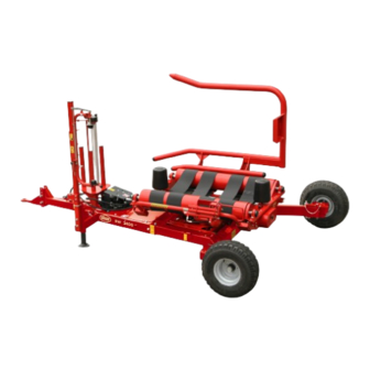
▬▬▬▬▬▬▬▬▬▬▬▬▬▬▬▬▬▬▬▬▬▬▬▬▬▬▬▬ technical information GENERAL DESCRIPTION OF THE MACHINE – The wrapper is a machine towed, designed and manufactured to wrap silage cylindrical bales and damp products using plastic film. All loading, winding and unloading operations are managed by an electronic control system, which is activated (in automatic or semi-au- tomatic mode) by the driver directly from the driver's seat in the tractor. - Page 22 ▬▬▬▬▬▬▬▬▬▬▬▬▬▬▬▬▬▬▬▬▬▬▬▬▬▬▬▬ technical information Main components Cutting unit (D) Reel unwinder unit (E) rotating table (C) Bale loading fork (B) Film reel (E1) "Lever" Moveable wheel control "Joystick" control Drawbar (A) Support Control system IDM-48301200701.tif A) Drawbar: it connects the machine to the tractor and its height can be adjusted to adapt to the towing eye of the tractor.
-
Page 23: Operation Cycle
▬▬▬▬▬▬▬▬▬▬▬▬▬▬▬▬▬▬▬▬▬▬▬▬▬▬▬▬ technical information OPERATION CYCLE – The machine moves forward until it centres the bale (A) on the loading fork (B), which col- lects the bale and positions it on the rotating table (C). – The rotating table (C) and the rollers (D) start to rotate simul- taneously to wrap the bale (A). -
Page 24: Areas Of Danger
▬▬▬▬▬▬▬▬▬▬▬▬▬▬▬▬▬▬▬▬▬▬▬▬▬▬▬▬ technical information AREAS OF DANGER The figure illustrates the danger zones where no-one should be when the machine is in use. It is the operator’s duty to keep such zones out of bounds; if necessary, (s)he should turn the engine off and clear out the danger zone. -
Page 25: Technical Data
▬▬▬▬▬▬▬▬▬▬▬▬▬▬▬▬▬▬▬▬▬▬▬▬▬▬▬▬ technical information TECHNICAL DATA Table 1: Technical data of the machine Description Unit of measurement Value Features of the machine Length 4320 Maximum pick-up width 3730 Transport width 2520 Maximum height 2300 Weight Bale hourly output n° Roller diameter Distance between the rollers 1110 ÷... - Page 26 ▬▬▬▬▬▬▬▬▬▬▬▬▬▬▬▬▬▬▬▬▬▬▬▬▬▬▬▬ technical information Table 1: Technical data of the machine Description Unit of measurement Value Dimensions of machine tyres 10.0/80 - 12.6 inflation pressure Tightening torque for wheel stud bolts Features of the film reel Maximum diameter of the reel Maximum height of the reel Film thickness micron...
-
Page 27: Allowable Slopes
▬▬▬▬▬▬▬▬▬▬▬▬▬▬▬▬▬▬▬▬▬▬▬▬▬▬▬▬ technical information ALLOWABLE SLOPES The image shows the maximum permissible slope in hard grounds, free from hollows and obstacles, with the machine in running order. Danger Warning Danger of overturning: do not use the machine in soils whose slope exceeds the allowed limit or in the presence of other ha- zards (rises, hollows, etc.), whi- ch could limit the stability of the... -
Page 28: Fittings On Demand
▬▬▬▬▬▬▬▬▬▬▬▬▬▬▬▬▬▬▬▬▬▬▬▬▬▬▬▬ technical information FITTINGS ON DEMAND The machine can be equipped with some fittings, upon demand in the order or later. The listed accessories can be in- stalled ONLY in the models of machines that are built in that way by the manufacturer. A) Reel support: it supports the backup film reel. -
Page 29: Safety Devices
▬▬▬▬▬▬▬▬▬▬▬▬▬▬▬▬▬▬▬▬▬▬▬▬▬▬▬▬ technical information SAFETY DEVICES The figure shows the position of the devices and the list reports their description and function. A) Rotating table safety bolt: in the event of excessive stress on the transmission, it is discon- nected to prevent damage to units or parts of the machine. -
Page 30: Oil-Pressure Devices
▬▬▬▬▬▬▬▬▬▬▬▬▬▬▬▬▬▬▬▬▬▬▬▬▬▬▬▬ technical information OIL-PRESSURE DEVICES The figure shows main components and the list reports their description and function. A) Hydraulic cylinder: it activates the ascent and descent of the loading fork. B) Hydraulic cylinder: it activates the ascent and descent of the rota- ting table. -
Page 31: Electronic And Electric Devices
▬▬▬▬▬▬▬▬▬▬▬▬▬▬▬▬▬▬▬▬▬▬▬▬▬▬▬▬ technical information ELECTRONIC AND ELECTRIC DEVICES The figure shows main componen- ts and the list reports their descrip- tion and function. A) Sensor: detects the number of revs and the position of the rota- ting table. B) Control unit: controls and commands the electrical devi- ces installed onto the machine. -
Page 32: Position Of Information And Safety Plates
▬▬▬▬▬▬▬▬▬▬▬▬▬▬▬▬▬▬▬▬▬▬▬▬▬▬▬▬ technical information POSITION OF INFORMATION AND SAFETY PLATES The figures indicate the position of the safety labels. Their meaning is de- scribed in paragraph "Description of safety signs". Important Make sure that all plates are legible. If they are not, clean or replace, if necessary, ensuring the new ones are placed in the original posi- tion. -
Page 33: Information About Handling And Loading Operations
▬▬▬▬▬▬▬▬▬▬▬▬▬▬▬ information about handling and loading operations INSTRUCTIONS FOR HANDLING AND LOADING Perform handling and loading operations by complying with the informa- tion supplied by the manufacturer, which is to be found in the machine and in user instructions. The people who are authorised to perform these operations, if necessary, will have to establish a "safety plan"... -
Page 34: Machine-Tractor Combination
▬▬▬▬▬▬▬▬▬▬▬▬▬▬▬ information about handling and loading operations 4. Suitably fasten the machine to the means of transport by means of ropes and chocks (see figure). 5. Make sure the loading gauge does not exceed the maximum admitted overall dimensions. If necessary, prepare suitable si- gns. -
Page 35: How To Couple The Machine To The Tractor
▬▬▬▬▬▬▬▬▬▬▬▬▬▬▬ information about handling and loading operations HOW TO COUPLE THE MACHINE TO THE TRACTOR Follow the instructions. 1. When receiving the machine, you must check the relevant category and the features of the tractor to which it must be coupled, so that you can assure its stability and correct operation. - Page 36 ▬▬▬▬▬▬▬▬▬▬▬▬▬▬▬ information about handling and loading operations How to connect the oil-pressure system 8. Thoroughly clean the quick cou- plings. 9. Connect the tubes (H-L) to the couplings of the distributor of the tractor. Important Use only original rapid action couplings, which guarantee a proper connection.
-
Page 37: How To Uncouple The Machine From The Tractor
▬▬▬▬▬▬▬▬▬▬▬▬▬▬▬ information about handling and loading operations The list contains the phases va- lid only for machines with "joy- stick" control. 12.Connect the connector(P) to socket(Q). 13.Connect the connector(R) to socket(S). 14.Connect the connector(T) to socket(U). 15.Connect the connector(V) to socket(Z). -
Page 38: How To Set The Height Of The Drawbar
▬▬▬▬▬▬▬▬▬▬▬▬▬▬▬ information about handling and loading operations 7. Remount the support foot (C) and fasten it with the pivot (G) and the safety pin (F). 8. Adjust the height of the support leg (C) using the handle (D). 9. Remove the locking pin (A) and the hitch pin (B) to disengage the tractor from the machine. -
Page 39: Assembly Of Plug For The Hydraulic Control Valve
▬▬▬▬▬▬▬▬▬▬▬▬▬▬▬ information about handling and loading operations ASSEMBLY OF PLUG FOR THE HYDRAULIC CONTROL VALVE The hydraulic control valve is ma- nufactured with the possibility of being transformed from an open- centred control valve to a closed- centred control valve. We recommend the transformation from an open-centred control valve to a closed-centred control valve... -
Page 40: User Information
▬▬▬▬▬▬▬▬▬▬▬▬▬▬▬▬▬▬▬▬▬▬▬▬▬▬▬▬▬▬ user information INSTRUCTIONS FOR USE AND OPERATION – The incidence of accidents that are caused by the use of machines depends on many factors, which cannot be prevented and controlled all the times. Some accidents can depend on unforeseeable environ- mental factors, while others mainly depend on the conduct of the ope- rator. -
Page 41: Description Of "Lever" Controls
▬▬▬▬▬▬▬▬▬▬▬▬▬▬▬▬▬▬▬▬▬▬▬▬▬▬▬▬▬▬ user information DESCRIPTION OF "LEVER" CONTROLS The list includes the description and the function of each control in- stalled on the machine. A) Lever: used to lift or lower the rotating table. B) Lever: used to rotate the rota- ting table (clockwise or anti- clockwise). -
Page 42: Description Of "Joystick" Controls
▬▬▬▬▬▬▬▬▬▬▬▬▬▬▬▬▬▬▬▬▬▬▬▬▬▬▬▬▬▬ user information DESCRIPTION OF "JOYSTICK" CONTROLS The list includes the description and the function of each control in- stalled on the machine. A) Lever: similar to a "Joystick" control and together with the non-release hold control (B) is used to actuate the functions li- sted. -
Page 43: Description Of The "Autostop" Control Unit
▬▬▬▬▬▬▬▬▬▬▬▬▬▬▬▬▬▬▬▬▬▬▬▬▬▬▬▬▬▬ user information Important Each time the hydraulic system is connected, it is necessary to pla- ce the lever of the distributor of the tractor in the oil flow position to activate the movements of the machine. DESCRIPTION OF THE "AUTOSTOP" CONTROL UNIT The list includes the description and the function of each control in- stalled on the machine. -
Page 44: Reset Counters
▬▬▬▬▬▬▬▬▬▬▬▬▬▬▬▬▬▬▬▬▬▬▬▬▬▬▬▬▬▬ user information 1. View home page. 2. Press one of the push buttons (B) to program the number of wrappings. The amount that can be pro- grammed, visualised in the va- lue (A3), ranges from 4 to 99. RESET COUNTERS Follow the instructions. -
Page 45: Programming Delayed Solenoid Actuation
▬▬▬▬▬▬▬▬▬▬▬▬▬▬▬▬▬▬▬▬▬▬▬▬▬▬▬▬▬▬ user information PROGRAMMING DELAYED SOLENOID ACTUATION The function allows to select the delay time for the actuation of the sole- noid so to have the starting of the turntable rotation without keeping the relative lever or joystick. Follow the instructions. 1. -
Page 46: Adjust Volume Acoustic Signal
▬▬▬▬▬▬▬▬▬▬▬▬▬▬▬▬▬▬▬▬▬▬▬▬▬▬▬▬▬▬ user information ADJUST VOLUME ACOUSTIC SIGNAL Follow the instructions. View home page. 1. Press push button (D) and hold (for at least 2 seconds) for ac- cess to the programming mo- des. 2. Repeatedly press one of the push buttons (B) until the page displayed is viewed. - Page 47 ▬▬▬▬▬▬▬▬▬▬▬▬▬▬▬▬▬▬▬▬▬▬▬▬▬▬▬▬▬▬ user information 2. Remove unwinding rollers using knob (A), and latch the lock(C) onto the pin (B). 3. Lower knob (D) to lift upper sup- port (E) and block it with stop device (L). Position knob (D) in the lower opening of the stop device (L) to block upper support in order to facilitate the feeding of the film...
-
Page 48: Preparing The Machine For Use
▬▬▬▬▬▬▬▬▬▬▬▬▬▬▬▬▬▬▬▬▬▬▬▬▬▬▬▬▬▬ user information 7. Manually unwind the film fol- lowing the instructions in the diagram and bring it in corre- spondence to the cutting unit. 8. Knot the end of the film and fa- sten it to bracket (G) in order to block it. -
Page 49: Bale Wrapping Mode ("Lever" Controls)
▬▬▬▬▬▬▬▬▬▬▬▬▬▬▬▬▬▬▬▬▬▬▬▬▬▬▬▬▬▬ user information BALE WRAPPING MODE ("LEVER" CONTROLS) Prevent unauthorised persons, especially children, old people and dome- stic animals from approaching the operating area when the machine is used. If it is necessary, immediately stop the machine and make people leave hazardous areas. -
Page 50: Bale Wrapping Mode ("Joystick" Controls)
▬▬▬▬▬▬▬▬▬▬▬▬▬▬▬▬▬▬▬▬▬▬▬▬▬▬▬▬▬▬ user information 7. When wrapping is finished, ro- tate the revolving table to the unloading position using the le- ver (B). 8. Lift the revolving table , using the lever (C) to unload the bale onto the ground. When the bale is unloaded, the film is cut and held by the cut- ting unit to wrap the next item. - Page 51 ▬▬▬▬▬▬▬▬▬▬▬▬▬▬▬▬▬▬▬▬▬▬▬▬▬▬▬▬▬▬ user information Follow the instructions. 1. Lower the loading fork using the lever (A). Caution Before actuating the loading fork, check that the safety devi- ce for the jack is disengaged. 2. Rotate revolving table (clockwise direction) to the loa- ding position using the lever (A).
- Page 52 ▬▬▬▬▬▬▬▬▬▬▬▬▬▬▬▬▬▬▬▬▬▬▬▬▬▬▬▬▬▬ user information 7. When wrapping is finished, ro- tate the revolving table to the unloading position using the le- ver (A). 8. Lift rotating table , by operating control (C), to upload the bale onto the ground. When the bale is unloaded, the film is cut and held by the cut- ting unit to wrap the next item.
-
Page 53: Indications To Produce Excellent Silage
▬▬▬▬▬▬▬▬▬▬▬▬▬▬▬▬▬▬▬▬▬▬▬▬▬▬▬▬▬▬ user information INDICATIONS TO PRODUCE EXCELLENT SILAGE The technique of sillaging forage collected in stacks of bales wrapped mechanically with plastic film started in northern Europe, as it has nume- rous benefits compared to traditional sillage systems (e.g. storing the fo- rage in vertical or horizontal silos, preserving the bale in polyethylene airtight bags, stack of bales covered with plastic film). - Page 54 ▬▬▬▬▬▬▬▬▬▬▬▬▬▬▬▬▬▬▬▬▬▬▬▬▬▬▬▬▬▬ user information The main features some listed below: – "mechanical" resistance in any type of application – adequate adhesive power to secure a strong sealing effect – resistance against UV rays to prevent the disintegrating action exer- ted by harmful radiations. Stocking the film reels The extendable film reels must be kept in the original packaging and pla- ced in a vertical position, protecting them against direct exposure to...
- Page 55 ▬▬▬▬▬▬▬▬▬▬▬▬▬▬▬▬▬▬▬▬▬▬▬▬▬▬▬▬▬▬ user information THE BALE IS PERFECT IF THE SWATH IS LOW AND LARGE Best results were obtained with a swath approx. 1.10m large and 0.30-0.40m high, both to prevent loss of product and to create well made bales. Benefits of a low and large swa- –...
- Page 56 ▬▬▬▬▬▬▬▬▬▬▬▬▬▬▬▬▬▬▬▬▬▬▬▬▬▬▬▬▬▬ user information Drawbacks of a high and narrow swath – Low progression – Low compression – Greater power absorption – Lower weight – Product loss – Water infiltration – Poor storage – After storage the bale may lose its shape C) Pressing the bales The bales obtained with the roto- presses must have even density levels, regular cylindrical shape and...
- Page 57 ▬▬▬▬▬▬▬▬▬▬▬▬▬▬▬▬▬▬▬▬▬▬▬▬▬▬▬▬▬▬ user information Large collector – progression diagram When the machine is fitted with a large collector it is possible to col- lect in regular swaths or swaths 190cm wide. When the swath is larger than the compression chamber, which means the lateral augers placed on top of the collector are involved, there is a straight progression, with...
- Page 58 ▬▬▬▬▬▬▬▬▬▬▬▬▬▬▬▬▬▬▬▬▬▬▬▬▬▬▬▬▬▬ user information elongate some types of films. The amount of plastic material needed to wrap a bale depends on the size of the bale itself, the number of desired layers, the mass of the film per surface unit ( the standard for the various films is about 22÷23 g/m²) and the pre-stretching levels.
- Page 59 ▬▬▬▬▬▬▬▬▬▬▬▬▬▬▬▬▬▬▬▬▬▬▬▬▬▬▬▬▬▬ user information Storing the wrapped bales A) Handling the bales The bales need to be handled with the maximum care and placed on a clean and flat surface to avoid a damaging the film with sharp or pointed objects. Danger Warning Any holes on the film must be repaired immediately using the spe-...
- Page 60 ▬▬▬▬▬▬▬▬▬▬▬▬▬▬▬▬▬▬▬▬▬▬▬▬▬▬▬▬▬▬ user information – The stacks of bales may represent a hazard. Forbid access to children – Wrapping may involve high noise levels, we recommend using the hearing protection headphones. – Carefully follow the instructions and recommendations of the manu- facturer of the machine.
-
Page 61: Format Change
▬▬▬▬▬▬▬▬▬▬▬▬▬▬▬▬▬▬▬▬▬▬▬▬▬▬▬▬▬▬ user information FORMAT CHANGE Before starting to work with characteristics that are different to the pre- vious, it is necessary to carry out some operations on the machine. Consult the table to find these operations. Table: Format change parameters Description References Positioning bale guide cones... -
Page 62: Change Reel Unwinding Ratio
▬▬▬▬▬▬▬▬▬▬▬▬▬▬▬▬▬▬▬▬▬▬▬▬▬▬▬▬▬▬ user information CHANGE REEL UNWINDING RATIO Follow the instructions. 1. Position the machine in a flat area, with the tractor stopped, the ignition key disconnected and with the wedges installed in the wheels of the bale wrapper. 2. Completely unscrew the handle (A) and disassemble the guard (B). -
Page 63: Set Film Pre-Stretching Value
▬▬▬▬▬▬▬▬▬▬▬▬▬▬▬▬▬▬▬▬▬▬▬▬▬▬▬▬▬▬ user information SET FILM PRE-STRETCHING VALUE Follow the instructions. 1. Position the machine in a flat area, with the tractor stopped, the ignition key disconnected and with the wedges installed in the wheels of the bale wrapper. 2. Remove guard (A). 3. -
Page 64: Road Circulation
▬▬▬▬▬▬▬▬▬▬▬▬▬▬▬▬▬▬▬▬▬▬▬▬▬▬▬▬▬▬ user information ROAD CIRCULATION Road circulation is allowed only for type-approved machines, which are towed by a tractor with suitable features and category. The driver of the tractor, which tows the machine, must comply with the requirements that are established by the laws in force. Before using the machine in public roads, check that its conditions are suitable (non-worn tyres and with suitable pressure, efficient lighting and signalling devices, compliant documents, etc.) in order to comply with the... -
Page 65: Putting The Machine Into Service
▬▬▬▬▬▬▬▬▬▬▬▬▬▬▬▬▬▬▬▬▬▬▬▬▬▬▬▬▬▬ user information Follow the instructions. – Uncouple the machine from the tractor (See "How to uncouple the machine from the tractor"). – Disconnect the electronic control system, and then store it in a dry and sheltered place. – Remove any residues of dust and products from all parts of the ma- chine. -
Page 66: Information About Adjustments
▬▬▬▬▬▬▬▬▬▬▬▬▬▬▬▬▬▬▬▬▬▬▬ information about adjustments INSTRUCTIONS FOR ADJUSTMENTS – Every operation, except for the cases in which it is expressly speci- fied, must be performed with tractor's engine turned off; furthermore, the ignition key must be disconnected and kept by the driver. The operator that is authorised to perform such operations will have to consider all necessary precautions to assure the safety of the invol- ved people in compliance with the requirements that meet the laws in... -
Page 67: Adjusting The Parallelism Of Bale Rotation Rollers
▬▬▬▬▬▬▬▬▬▬▬▬▬▬▬▬▬▬▬▬▬▬▬ information about adjustments ADJUSTING THE PARALLELISM OF BALE ROTATION ROLLERS The figure shows the points of ope- ration and the description provides the procedures to be adopted. 1. Position the machine on a flat and robust surface. 2. Block the machine wheels with wedges (if it is not connected to the tractor) in order to avoid sud- den movements. -
Page 68: Adjustment Of Film Cutting Cam
▬▬▬▬▬▬▬▬▬▬▬▬▬▬▬▬▬▬▬▬▬▬▬ information about adjustments ADJUSTMENT OF FILM CUTTING CAM Expert technician The figure shows the points of operation and the description provides the procedures to be adopted. "LEVER" CONTROL "JOYSTICK" CONTROL 1. Position the machine on a flat and robust surface. –... -
Page 69: Adjustment Of Film Cutting Unit
▬▬▬▬▬▬▬▬▬▬▬▬▬▬▬▬▬▬▬▬▬▬▬ information about adjustments ADJUSTMENT OF FILM CUTTING UNIT The figure shows the points of ope- ration and the description provides the procedures to be adopted. 1. Position the machine on a flat and robust surface. – The operation must be per- formed when the machine is connected to the tractor, whi- ch must be stopped in safe... -
Page 70: Adjustment Of Cutting Unit Opening
▬▬▬▬▬▬▬▬▬▬▬▬▬▬▬▬▬▬▬▬▬▬▬ information about adjustments 7. Make a test wrap in order to understand if the operation has been per- formed correctly. ADJUSTMENT OF CUTTING UNIT OPENING Expert technician The figure shows the points of ope- ration and the description provides the procedures to be adopted. -
Page 71: Maintenance Information
▬▬▬▬▬▬▬▬▬▬▬▬▬▬▬▬▬▬▬▬▬▬▬▬▬▬ maintenance information INSTRUCTIONS FOR MAINTENANCE – Even though the machine was designed and manufactured to work in hard environmental conditions, you have to carry out scheduled main- tenance interventions. Correct maintenance will allow achieving the best performance, a longer duration of work and a constant preserva- tion of safety requirements. -
Page 72: Lubricant Table
▬▬▬▬▬▬▬▬▬▬▬▬▬▬▬▬▬▬▬▬▬▬▬▬▬▬ maintenance information Table 3: Intervals of periodic maintenance Frequency Component Type of intervention Reference Check the wearing Transmission chains condition of pinions and chains. Check the efficiency and, See "How to replace the Safety bolt if necessary, replace it safety bolt"... -
Page 73: Driving Torque Table
▬▬▬▬▬▬▬▬▬▬▬▬▬▬▬▬▬▬▬▬▬▬▬▬▬▬ maintenance information DRIVING TORQUE TABLE Check all the elements of the fastening of the various components of the machine with a dynamometric key. Respect the driving torque indicated in the table. Important Such values have been obtained experimentally and for serial appli- cations, one is advised to check them with field tests. -
Page 74: Lubrication Points Diagram
▬▬▬▬▬▬▬▬▬▬▬▬▬▬▬▬▬▬▬▬▬▬▬▬▬▬ maintenance information LUBRICATION POINTS DIAGRAM Follow the instructions. 1. Position the machine in a flat area, with the tractor stopped, the igni- tion key disconnected and with the wedges installed in the wheels of the bale wrapper. 2. Carefully clean all of the interested parts and the lubrication points so as to not mix the lubricant with impurities. -
Page 75: Changing Oil Filter Cartridge
▬▬▬▬▬▬▬▬▬▬▬▬▬▬▬▬▬▬▬▬▬▬▬▬▬▬ maintenance information CHANGING OIL FILTER CARTRIDGE Follow the instructions. 1. Position the machine in a flat area, with the tractor stopped, the ignition key disconnected and with the wedges installed in the wheels of the bale wrapper. 2. Remove guard (A). 3. -
Page 76: Battery Charging Mode
▬▬▬▬▬▬▬▬▬▬▬▬▬▬▬▬▬▬▬▬▬▬▬▬▬▬ maintenance information BATTERY CHARGING MODE The figure shows the points of ope- ration and the description provides the procedures to be adopted. 1. Position the machine on a flat and robust surface. 2. Block the machine wheels with wedges (if it is not connected to the tractor) in order to avoid sudden movements. -
Page 77: Failure Information
▬▬▬▬▬▬▬▬▬▬▬▬▬▬▬▬▬▬▬▬▬▬▬▬▬▬▬▬▬ failure information TROUBLES, CAUSES, REMEDIES – The purpose of the following information is to identify and correct pos- sible faults and malfunctions that may occur when using the machine. – The various irregularities that may occur were divided into tables, ac- cording to the reference operator unit. - Page 78 ▬▬▬▬▬▬▬▬▬▬▬▬▬▬▬▬▬▬▬▬▬▬▬▬▬▬▬▬▬ failure information Table 7: Operation irregularities of the machine Trouble Cause Cure Load bales in the correct cylindrical shape (See "indications to produce Excessively irregular shape of the excellent silage"). bale. Wrap the bale within a brief period of Difficulty in loading the bale the baling phase.
- Page 79 ▬▬▬▬▬▬▬▬▬▬▬▬▬▬▬▬▬▬▬▬▬▬▬▬▬▬▬▬▬ failure information Table 9: Malfunction of the cutting unit Trouble Cause Cure Replace the blade (See "Replace the blade of the film cutter"). Cutting blade is worn out. Caution Wear protective gloves for this operation. Adjust the position of cutting blade The cutting blade is not adjusted (See "Adjustment of film cutting correctly...
-
Page 80: Information About Replacements
▬▬▬▬▬▬▬▬▬▬▬▬▬▬▬▬▬▬▬▬▬▬▬ information about replacements INSTRUCTIONS FOR PART REPLACEMENT – Every operation, except for the cases in which it is expressly speci- fied, must be performed with tractor's engine turned off; furthermore, the ignition key must be disconnected and kept by the driver. The operator that is authorised to perform such operations will have to consider all necessary precautions to assure the safety of the invol- ved people in compliance with the requirements that meet the laws in... -
Page 81: How To Replace The Safety Bolt
▬▬▬▬▬▬▬▬▬▬▬▬▬▬▬▬▬▬▬▬▬▬▬ information about replacements 9. Lower the machine, and then tighten the nuts (B). 10.Inflate the tyre until reaching the pressure that is specified in the chart (See "Technical Data"). 11.Remove the lifting device (C) when the operation is complete. 12.Remove the safety wedges (A). -
Page 82: Machine Disposal
▬▬▬▬▬▬▬▬▬▬▬▬▬▬▬▬▬▬▬▬▬▬▬ information about replacements MACHINE DISPOSAL In phase of abandonment, it is necessary to carry out a series of inter- ventions so that the machine and all of its devices do not constitute an obstacle and so that they are not easily accessible. To avoid that the machine might constitute dangers for persons and the environment, it is necessary to disconnect and render all the feeds unu- sable (electric, pneumatic, hydraulic, etc.) and to remove any possible li-... - Page 83 ▬▬▬▬▬▬▬▬▬▬▬▬▬▬▬▬▬▬▬▬▬▬▬ information about replacements - 77 - English...
-
Page 84: Annexes
▬▬▬▬▬▬▬▬▬▬▬▬▬▬▬▬▬▬▬▬▬▬▬▬▬▬▬▬▬▬▬▬▬ Annexes Table 9: components of the electrical system Reference to Reference Code Name photo no. the table Autostop control unit MT00001617 ESD A09 Supply cable CAN MT00001619 ESD A08 Signal cable MT00001618 ESD A10 Supply cable MT00001620 ESD A11 Signal cable MT00001549 Sensor (M18) - Page 85 ▬▬▬▬▬▬▬▬▬▬▬▬▬▬▬▬▬▬▬▬▬▬▬▬▬▬▬▬▬▬▬▬▬ Annexes - 79 - English...
-
Page 86: (To Serial Number 163145)
▬▬▬▬▬▬▬▬▬▬▬▬▬▬▬▬▬▬▬▬▬▬▬▬▬▬▬▬▬▬▬▬▬ Annexes Table 10: components of the electrical system Reference to Reference Code Name photo no. the table Autostop control unit MT00001617 ESD A09 Supply cable CAN MT00001619 ESD A08 Signal cable MT00001618 ESD A10 Supply cable MT00001620 ESD A11 Signal cable MT00001549 Sensor (M18) - Page 87 ▬▬▬▬▬▬▬▬▬▬▬▬▬▬▬▬▬▬▬▬▬▬▬▬▬▬▬▬▬▬▬▬▬ Annexes - 81 - English...
-
Page 88: Wiring Diagram With "Joystick" Controls
▬▬▬▬▬▬▬▬▬▬▬▬▬▬▬▬▬▬▬▬▬▬▬▬▬▬▬▬▬▬▬▬▬ Annexes Table 11: components of the electrical system Reference to Reference Code Name photo no. the table Autostop control unit MT00001617 ESD A09 Supply cable CAN MT00001619 ESD A08 Signal cable MT00001549 Sensor (M18) PBA + A01 + A04 MT00001615 Autostop control unit complete K2 (J2 + ECJ + D) - Page 89 ▬▬▬▬▬▬▬▬▬▬▬▬▬▬▬▬▬▬▬▬▬▬▬▬▬▬▬▬▬▬▬▬▬ Annexes - 83 - English...
-
Page 90: Wiring Diagram "Joystick" (To Serial Number163145)
▬▬▬▬▬▬▬▬▬▬▬▬▬▬▬▬▬▬▬▬▬▬▬▬▬▬▬▬▬▬▬▬▬ Annexes WIRING DIAGRAM "JOYSTICK" (TO SERIAL NUMBER163145) English - 84 -... -
Page 91: Wiring Diagram "Joystick" (From Serial Number 163146)
▬▬▬▬▬▬▬▬▬▬▬▬▬▬▬▬▬▬▬▬▬▬▬▬▬▬▬▬▬▬▬▬▬ Annexes WIRING DIAGRAM "JOYSTICK" (FROM SERIAL NUMBER 163146) - 85 - English... -
Page 92: Wiring Diagram Control Unit
▬▬▬▬▬▬▬▬▬▬▬▬▬▬▬▬▬▬▬▬▬▬▬▬▬▬▬▬▬▬▬▬▬ Annexes WIRING DIAGRAM CONTROL UNIT English - 86 -... -
Page 93: Wiring Diagram Hydraulic Control Valve With "Joystick" Controls
▬▬▬▬▬▬▬▬▬▬▬▬▬▬▬▬▬▬▬▬▬▬▬▬▬▬▬▬▬▬▬▬▬ Annexes WIRING DIAGRAM HYDRAULIC CONTROL VALVE WITH CON "JOYSTICK" CONTROLS - 87 - English... -
Page 94: Wiring Diagram Signal Cable For Autostop Control Unit
▬▬▬▬▬▬▬▬▬▬▬▬▬▬▬▬▬▬▬▬▬▬▬▬▬▬▬▬▬▬▬▬▬ Annexes WIRING DIAGRAM SIGNAL CABLE FOR AUTOSTOP CONTROL UNIT English - 88 -... -
Page 95: Wiring Diagram Supply Cable Can Autostop Control Unit
▬▬▬▬▬▬▬▬▬▬▬▬▬▬▬▬▬▬▬▬▬▬▬▬▬▬▬▬▬▬▬▬▬ Annexes WIRING DIAGRAM SUPPLY CABLE CAN AUTOSTOP CONTROL UNIT - 89 - English... -
Page 96: Wiring Diagram Supply Cable
▬▬▬▬▬▬▬▬▬▬▬▬▬▬▬▬▬▬▬▬▬▬▬▬▬▬▬▬▬▬▬▬▬ Annexes WIRING DIAGRAM SUPPLY CABLE English - 90 -... -
Page 97: Wiring Diagram Signal Cable
▬▬▬▬▬▬▬▬▬▬▬▬▬▬▬▬▬▬▬▬▬▬▬▬▬▬▬▬▬▬▬▬▬ Annexes WIRING DIAGRAM SIGNAL CABLE - 91 - English... -
Page 98: Wiring Diagram Cable (3521962)
▬▬▬▬▬▬▬▬▬▬▬▬▬▬▬▬▬▬▬▬▬▬▬▬▬▬▬▬▬▬▬▬▬ Annexes WIRING DIAGRAM CABLE (3521962) English - 92 -... -
Page 99: Wiring Diagram Cable (3521963)
▬▬▬▬▬▬▬▬▬▬▬▬▬▬▬▬▬▬▬▬▬▬▬▬▬▬▬▬▬▬▬▬▬ Annexes WIRING DIAGRAM CABLE (3521963) - 93 - English... -
Page 100: Wiring Diagram Cable (3521971)
▬▬▬▬▬▬▬▬▬▬▬▬▬▬▬▬▬▬▬▬▬▬▬▬▬▬▬▬▬▬▬▬▬ Annexes WIRING DIAGRAM CABLE (3521971) English - 94 -... -
Page 101: Wiring Diagram Cable (3521972)
▬▬▬▬▬▬▬▬▬▬▬▬▬▬▬▬▬▬▬▬▬▬▬▬▬▬▬▬▬▬▬▬▬ Annexes WIRING DIAGRAM CABLE (3521972) - 95 - English... -
Page 102: Picture
▬▬▬▬▬▬▬▬▬▬▬▬▬▬▬▬▬▬▬▬▬▬▬▬▬▬▬▬▬▬▬▬▬ Annexes PICTURE 3 PICTURE 2 PICTURE 1 PICTURE 6 PICTURE 4 PICTURE 5 PICTURE English - 96 -... -
Page 103: Hydraulic System
▬▬▬▬▬▬▬▬▬▬▬▬▬▬▬▬▬▬▬▬▬▬▬▬▬▬▬▬▬▬▬▬▬ Annexes Table 13: components of the hydraulic system Reference to Reference Code Name the table A+B+C+D HSD A01 Hydraulic system diagram with "lever" controls A+B+C+J HSD A02 Hydraulic system diagram with "joystick" controls 3544860 HSD A03 Hydraulic control valve with "lever" controls 3544921 HSD A04 Hydraulic control valve with "joystick"... -
Page 104: Hydraulic System Diagram With "Lever" Controls
▬▬▬▬▬▬▬▬▬▬▬▬▬▬▬▬▬▬▬▬▬▬▬▬▬▬▬▬▬▬▬▬▬ Annexes Table 13: components of the electrical system Technical Reference Code Name specifications 8859916 Bale loading fork actuating jack 8859720 Table tilting actuating jack 3311500 Ø 1,25 mm Single-acting throttle valve 3411700 Ø 1 mm Single-acting throttle valve 8859085 Hydraulic motor for table rotation 8863560 Overload valve... - Page 105 ▬▬▬▬▬▬▬▬▬▬▬▬▬▬▬▬▬▬▬▬▬▬▬▬▬▬▬▬▬▬▬▬▬ Annexes - 99 - English...
-
Page 106: Hydraulic System Diagram With "Joystick" Controls
▬▬▬▬▬▬▬▬▬▬▬▬▬▬▬▬▬▬▬▬▬▬▬▬▬▬▬▬▬▬▬▬▬ Annexes Table 14: components of the electrical system Technical Reference Code Name specifications 8859916 Bale loading fork actuating jack 8863565 Stop valve 8859720 Table tilting actuating jack 8859085 Hydraulic motor for table rotation 8863560 Overload valve 3544921 Hydraulic control valve with "joystick" controls Loading fork lifting valve Loading fork lowering valve Revolving table lifting valve... - Page 107 ▬▬▬▬▬▬▬▬▬▬▬▬▬▬▬▬▬▬▬▬▬▬▬▬▬▬▬▬▬▬▬▬▬ Annexes - 101 - English...
-
Page 108: Hydraulic Control Valve With "Lever" Controls
▬▬▬▬▬▬▬▬▬▬▬▬▬▬▬▬▬▬▬▬▬▬▬▬▬▬▬▬▬▬▬▬▬ Annexes HYDRAULIC CONTROL VALVE WITH "LEVER" CONTROLS English - 102 -... -
Page 109: Hydraulic Control Valve With "Joystick" Controls
▬▬▬▬▬▬▬▬▬▬▬▬▬▬▬▬▬▬▬▬▬▬▬▬▬▬▬▬▬▬▬▬▬ Annexes HYDRAULIC CONTROL VALVE WITH "JOYSTICK" CONTROLS - 103 - English... -
Page 110: Cutting Unit Hydraulic System Diagram
▬▬▬▬▬▬▬▬▬▬▬▬▬▬▬▬▬▬▬▬▬▬▬▬▬▬▬▬▬▬▬▬▬ Annexes Table 16: components of the hydraulic system Technical Reference Code Name specifications 8859928 Cutting unit driving jack 8863574 Accumulator 8863573 Cutting unit start valve 8858258 Hydraulic pump 8863576 70 bar Pressure control valve CUTTING UNIT HYDRAULIC SYSTEM DIAGRAM English - 104 -... - Page 111 ▬▬▬▬▬▬▬▬▬▬▬▬▬▬▬▬▬▬▬▬▬▬▬▬▬▬▬▬▬▬▬▬▬ Annexes - 105 - English...
- Page 112 ▬▬▬▬▬▬▬▬▬▬▬▬▬▬▬▬▬▬▬▬▬▬▬▬▬▬▬▬▬▬▬▬▬ Annexes English - 106 -...
- Page 113 ▬▬▬▬▬▬▬▬▬▬▬▬▬▬▬▬▬▬▬▬▬▬▬▬▬▬▬▬▬▬ Analitical index Adjust volume acoustic signal How to couple the machine to the tractor How to connect the electric system Adjust volume control key activation How to connect the electronic control Adjusting the parallelism of bale rotation rollers system How to connect the oil-pressure system Adjusting the tension of the roller transmission How to connect the towing eye to the eye of...
- Page 114 ▬▬▬▬▬▬▬▬▬▬▬▬▬▬▬▬▬▬▬▬▬▬▬▬▬▬▬▬▬▬ Analitical index Machine-tractor combination Maintenance, instructions for Technical data Manufacturer and machine identification Troubles, causes, remedies Night work Unpacking and packing Use and operation, instructions for Obligations of the employer Oil-pressure devices Wiring diagram "joystick" (from serial number 163146) Operation and use, instructions for Wiring diagram "joystick"...
Need help?
Do you have a question about the BW 2400 M and is the answer not in the manual?
Questions and answers