Sign In
Upload
Download
Table of Contents
Contents
Add to my manuals
Delete from my manuals
Share
URL of this page:
HTML Link:
Bookmark this page
Add
Manual will be automatically added to "My Manuals"
Print this page
×
Bookmark added
×
Added to my manuals
Manuals
Brands
Vicon Manuals
Farm Equipment
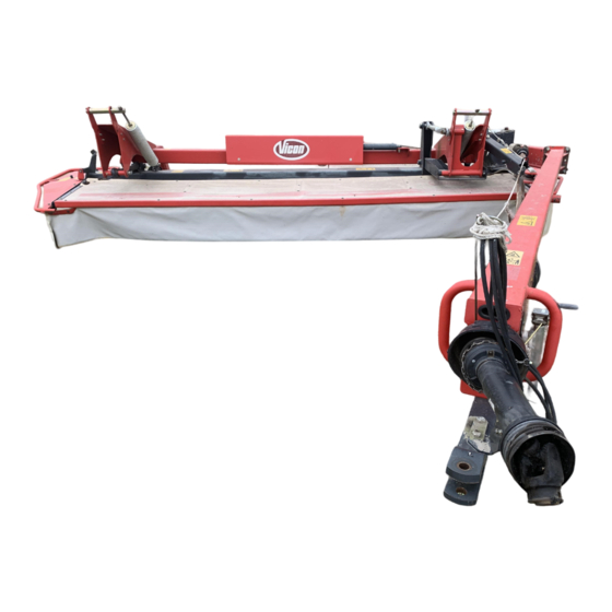
KM 2800
Operator's manual
Vicon KM 2800 Operator's Manual
Hide thumbs
1
2
Table Of Contents
3
4
5
6
7
8
9
10
11
12
13
14
15
16
17
18
19
20
21
22
23
24
25
26
27
28
29
30
31
32
33
34
35
36
37
38
39
page
of
39
Go
/
39
Contents
Table of Contents
Bookmarks
Table of Contents
Table of Contents
Declaration of Conformity
General Description
Preface
Technical Specifications
Safety Instructions
Danger Sticker Explanation Texts
Assembly Instruction KM2800/3200/4000
Assembly Instruction KM4000S
Adjusting Transport Width KM4000S
Preparing the Tractor
Hydraulic Connection
Attaching to the Tractor
Mounting the Coupling Shaft
Shortening Procedure Coupling Shaft
Cutting Height
Mowing Stony Fields
Wide Inserts
Ground Pressure Adjustment
Mowing
Directions for Proper Mowing
Transport Position KM2800/3200/4000
Operating Position KM2800/3200/4000
Transport Position KM4000S
Operating Position KM4000S
Transport
Parking
Lubrication Chart
Tyres
Maintenance
Exchanging Blades
Inspecting and Changing Oil Gearboxes
Checking and Changing Oil Cutterbar
Inspection of Nuts and Bolts
Timing the Discs
Hydraulic System
Accessories
Torques
Trouble Shooting Chart
Advertisement
Quick Links
1
Table of Contents
2
Technical Specifications
3
Lubrication Chart
4
Maintenance
5
Inspecting and Changing Oil Gearboxes
6
Checking and Changing Oil Cutterbar
Download this manual
KM 2800-3200-4000-4000S
Operator´s Manual
Translation of the original operator's manual
Date of publication
Date printed
Language
Valid as from serial No.:
Reference No:
Index
06/2011
06/2011
EN
KT 418.065
90061200EN
2011-06
Table of
Contents
Previous
Page
Next
Page
1
2
3
4
5
Advertisement
Table of Contents
Need help?
Do you have a question about the KM 2800 and is the answer not in the manual?
Ask a question
Questions and answers
Related Manuals for Vicon KM 2800
Farm Equipment Vicon KM 3200 Operator's Manual
(39 pages)
Farm Equipment Vicon KM 4000 Operator's Manual
(39 pages)
Farm Equipment Vicon RV 1601 Operation Manual
(108 pages)
Farm Equipment Vicon EXTRA 632 T Operator's Manual
(98 pages)
Farm Equipment Vicon Extra 532 Service Manual
Trailed plain mower (90 pages)
Farm Equipment Vicon Extra 117 Operating Manual
(96 pages)
Farm Equipment Vicon CM 299 Operation Manual
(65 pages)
Farm Equipment Vicon EXTRA 632 FR Operator's Manual
(130 pages)
Farm Equipment Vicon EXTRA 228 Operator's Manual
(96 pages)
Farm Equipment Vicon Extra 828T PRO Instruction Manual
(172 pages)
Farm Equipment Vicon RF121 R Operation Manual
(61 pages)
Farm Equipment Vicon Fanex 523 T Operation Manual
(34 pages)
Farm Equipment Vicon Extra 328 Operating Manual
(111 pages)
Farm Equipment Vicon Andex 714 T Vario Operating Manual
(96 pages)
Farm Equipment Vicon Andex 714 T Evo Operating Manual
(92 pages)
Farm Equipment Vicon EXTRA 624 T Assembly Instructions Manual
(16 pages)
This manual is also suitable for:
Km 3200
Km 4000
Km 4000s
Table of Contents
Save PDF
Print
Rename the bookmark
Delete bookmark?
Delete from my manuals?
Login
Sign In
OR
Sign in with Facebook
Sign in with Google
Upload manual
Upload from disk
Upload from URL


Need help?
Do you have a question about the KM 2800 and is the answer not in the manual?
Questions and answers