
Related Manuals for Vicon BW 2100 C


Summary of Contents for Vicon BW 2100 C
- Page 1 BW 2100 C Operation and maintenance manual Edition 03/2013 Printing date Language Series I ► Serial number n.KB 165100 Code 9820D17GB...
- Page 3 BW 2100 C WRAPPER FOR CYLINDRICAL BALES Keep this manual in a well-known and easily accessible place, in order to have it always at disposal when you need to read it. The user and maintenance information, which is an integral part of agricultural machinery, MUST ALWAYS BE KEPT IN THE DRIVER'S SEAT of the tractor to which the machine is combined.
- Page 4 The reproduction, even partial, of this document is prohibited without authorization from the builder. The builder is engaged in a program of continuous improvement and reserves the right to modify this document without any obligation to provide advance notice so long as it is no safety risk. 2013©...
- Page 5 Kverneland Group Ravenna Srl Via Alcide De Gasperi 34 - 48026 - Russi (RA) - ITALY BW2100 - BW2250 - BW2400 - BW2600 - BW2850 164700 - 168000 Mr. Claus Udengaard Thomsen Mr. Claus Udengaard Thomsen-CEO of Kverneland Group Ravenna Srl Russi, 01/01/2013 DICHIARAZIONE CE DI CONFORMITÀ...
- Page 6 Kverneland Group Ravenna Srl Via Alcide De Gasperi 34 - 48026 - Russi (RA) - ITALY BW2100 - BW2250 - BW2400 - BW2600 - BW2850 164700 - 168000 Mr. Claus Udengaard Thomsen IZJAVA ES O SKLADNOSTI EF-SAMSVARSERKLÆRING Podjetje (1) izjavlja pod lastno odgovornostjo, da je kmetijski stroj s funkcijo Selskapet (1) bekrefter under dets ansvar at landbruksmaskinene med BALIRNICE v navedenih modelih (2), ki jih je mogoče identificirati na podlagi funksjonene RUNDBALLPAKKER realisert med modellene som er oppført (2)
-
Page 7: Table Of Contents
▬▬▬▬▬▬▬▬▬▬▬▬▬▬▬▬▬▬▬▬▬▬▬▬▬▬▬▬▬▬▬▬▬Summary GENERAL INFORMATION INFORMATION ABOUT ADJUSTMENTS purpose of this manual ..........3 instructions for adjustments .........48 Manufacturer and machine identification .......4 Adjusting the parallelism of bale rotation rollers ..48 Procedure to request technical assistance....4 Adjusting the tension of the roller transmission glossary and terminology..........4 chains ................49 Attached documentation ..........5... - Page 8 ▬▬▬▬▬▬▬▬▬▬▬▬▬▬▬▬▬▬▬▬▬▬▬▬▬▬▬▬▬▬▬▬▬Summary - 2 - English...
-
Page 9: General Information
▬▬▬▬▬▬▬▬▬▬▬▬▬▬▬▬▬▬▬▬▬▬▬▬▬▬▬▬ general information PURPOSE OF THIS MANUAL – The purpose of the manual, which is an integral part of the machine, is to raise awareness among users to pay attention during the man- machine interaction. – The manual has been created by the manufacturer to transfer infor- mation and instructions to minimise risks. -
Page 10: Manufacturer And Machine Identification
▬▬▬▬▬▬▬▬▬▬▬▬▬▬▬▬▬▬▬▬▬▬▬▬▬▬▬▬ general information Expert technician The symbol indicates operations to be carried out ONLY by author- ised technicians with skills in the relevant sector. MANUFACTURER AND MACHINE IDENTIFICATION The displayed identification plate is directly stuck on the machine. It lists traceability details and refer- ences to be used when asking for technical support and/or ordering spare parts. -
Page 11: Attached Documentation
▬▬▬▬▬▬▬▬▬▬▬▬▬▬▬▬▬▬▬▬▬▬▬▬▬▬▬▬ general information – Routine maintenance: set of operations that are necessary to keep the functionality, the efficiency and the safety requirements of the ma- chine. The manufacturer establishes the intervals between the inter- ventions and, if necessary, also establishes the performance modes for those operations that imply particular procedures. -
Page 12: Safety Information
▬▬▬▬▬▬▬▬▬▬▬▬▬▬▬▬▬▬▬▬▬▬▬▬▬▬▬▬▬ safety information REASONABLY FORESEEABLE INCORRECT USES – DO NOT ever let users who have not been adequately trained, in- formed and authorised use the machine. – DO NOT ever let users who are not capable of reading and under- standing the user manual and who are not capable of recognising safety signs use the machine. -
Page 13: Residual Risks
▬▬▬▬▬▬▬▬▬▬▬▬▬▬▬▬▬▬▬▬▬▬▬▬▬▬▬▬▬ safety information – DO NOT leave the machine in a place where it may represent an ob- struction or hazard for outsiders. Park it in a flat area on the stable surface. – In case of improper use of the machine, the operator assumes the responsibilities (moral, civil and criminal) for the damages caused to people or things. -
Page 14: General Safety Rules
▬▬▬▬▬▬▬▬▬▬▬▬▬▬▬▬▬▬▬▬▬▬▬▬▬▬▬▬▬ safety information – The employer should compile the information transferred to the users adequately, so that these can be presented in the event of litigation. GENERAL SAFETY RULES – When designing and manufacturing the machine, the Manufacturer paid special attention to the aspects that may endanger the safety and health of the people working with the machine. -
Page 15: Safety Rules About Use And Operation
▬▬▬▬▬▬▬▬▬▬▬▬▬▬▬▬▬▬▬▬▬▬▬▬▬▬▬▬▬ safety information SAFETY RULES ABOUT USE AND OPERATION – The operator of the machine (driver) must have competences and skills that are suitable to the type of work to be performed, and his/her conditions must be appropriate to perform the activity in a safe way. –... -
Page 16: Safety Rules About Road Circulation
▬▬▬▬▬▬▬▬▬▬▬▬▬▬▬▬▬▬▬▬▬▬▬▬▬▬▬▬▬ safety information – In case of steep soils, adapt the speed of the machine ac- cording to the slope and the stability of the soil. – Unload the bale so that there is no risk of sudden and uncon- trolled movements when work- ing on sloping ground. -
Page 17: Safety Rules About Maintenance And Adjustments
▬▬▬▬▬▬▬▬▬▬▬▬▬▬▬▬▬▬▬▬▬▬▬▬▬▬▬▬▬ safety information SAFETY RULES ABOUT MAINTENANCE AND ADJUSTMENTS – Keep the machine in maximum efficiency conditions and carry out the scheduled maintenance recommended by the Manufacturer. Good maintenance ensures the best performance, a longer work life and the constant maintenance of the safety requirements. –... -
Page 18: Safety Rules For The Environmental Impact
▬▬▬▬▬▬▬▬▬▬▬▬▬▬▬▬▬▬▬▬▬▬▬▬▬▬▬▬▬ safety information SAFETY RULES FOR THE ENVIRONMENTAL IMPACT – The Waste of Electrical and Electronic Equipment may contain dan- gerous substances with potentially harmful effects on the environ- ment and on people. It is recommended to correctly dispose them. –... - Page 19 ▬▬▬▬▬▬▬▬▬▬▬▬▬▬▬▬▬▬▬▬▬▬▬▬▬▬▬▬▬ safety information –Danger of body crushing: prior to intervening in zones of potential danger, insert the safety block. –Danger of catching: when the motor is running, do not open or remove the protections. –Danger of catching: when the motor is running, do not open or remove the protections.
- Page 20 ▬▬▬▬▬▬▬▬▬▬▬▬▬▬▬▬▬▬▬▬▬▬▬▬▬▬▬▬▬ safety information –Danger of body crushing: upload the bale in order to prevent the risk of sudden and un- controlled movements (for example, in case of extremely steep soils). –Crashing hazard for the body: DO NOT STOP in the machine's range of action when the loading fork is activated.
-
Page 21: Technical Information
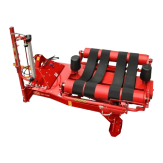
▬▬▬▬▬▬▬▬▬▬▬▬▬▬▬▬▬▬▬▬▬▬▬▬▬▬▬▬ technical information GENERAL DESCRIPTION OF THE MACHINE – The wrapper is a machine towed, designed and manufactured to wrap silage cylindrical bales and damp products using plastic film. All the wrapping and unloading stages are controlled by an electronic system, activated (in automatic or semi-automatic mode) by the driv- er, directly in the driver's seat of the tractor. - Page 22 ▬▬▬▬▬▬▬▬▬▬▬▬▬▬▬▬▬▬▬▬▬▬▬▬▬▬▬▬ technical information Main components Film reel (D1) Cutting uni (C)t Reel unwinder unit (D) Reel support (F) rotating table (B) Reel support (F) Electronic control system (E) 3-point connection (A) Support (G) A) 3-point connection: connects the machine to the lifting unit of the tractor.
-
Page 23: Operation Cycle
▬▬▬▬▬▬▬▬▬▬▬▬▬▬▬▬▬▬▬▬▬▬▬▬▬▬▬▬ technical information OPERATION CYCLE – Pick-up the bale (A) with a spe- cial lifting device and position it on the rotating table (B). – The rotating table (B) and the rollers (C) start to rotate simul- taneously to wrap the bale (A). –... -
Page 24: Areas Of Danger
▬▬▬▬▬▬▬▬▬▬▬▬▬▬▬▬▬▬▬▬▬▬▬▬▬▬▬▬ technical information AREAS OF DANGER The figure illustrates the danger zones where no-one should be when the machine is in use. It is the operator’s duty to keep such zones out of bounds; if necessary, (s)he should turn the engine off and clear out the danger zone. -
Page 25: Technical Data
▬▬▬▬▬▬▬▬▬▬▬▬▬▬▬▬▬▬▬▬▬▬▬▬▬▬▬▬ technical information TECHNICAL DATA Table 1: Technical data of the machine Description Unit of measurement Value Features of the machine Length 2700 Transport width 1620 Maximum height 1750 Weight Bale hourly output n° 50 ÷ 60 Roller diameter Distance between the rollers 1110 ÷... - Page 26 ▬▬▬▬▬▬▬▬▬▬▬▬▬▬▬▬▬▬▬▬▬▬▬▬▬▬▬▬ technical information Table 1: Technical data of the machine Description Unit of measurement Value Maximum height of the reel Film thickness micron 25 ÷ 35 Film pre-stretch Overlapping Features of the bale Diameter (min÷max) 1200 ÷ 1500 Width 1300 Weight 1000 Tractor requirements...
-
Page 27: Supplied Fittings
▬▬▬▬▬▬▬▬▬▬▬▬▬▬▬▬▬▬▬▬▬▬▬▬▬▬▬▬ technical information SUPPLIED FITTINGS A series of spanners and tools are supplied with the machine. These are placed inside the tool box on the side of the machine: A) Use and maintenance manual contained in a nylon bag B) hex key to remove parts of the machine (8-10) (10-13) (17-19) C) Rotating table safety bolt: in... -
Page 28: Safety Devices
▬▬▬▬▬▬▬▬▬▬▬▬▬▬▬▬▬▬▬▬▬▬▬▬▬▬▬▬ technical information Important The mounting of the accessories, when requested after the pur- chase of the machine, has to be carried out by personnel with pre- cise technical competency, in repair shops that are adequately equipped and authorised by the manufacturer. Whoever carries out the installation of an accessory should issue a document that certifies that the mounting has been carried out in a repair shop that has been authorised by the manufacturer. -
Page 29: Oil-Pressure Devices
▬▬▬▬▬▬▬▬▬▬▬▬▬▬▬▬▬▬▬▬▬▬▬▬▬▬▬▬ technical information OIL-PRESSURE DEVICES The figure shows main components and the list reports their description and function. A) Hydraulic cylinder: it activates the ascent and descent of the rotat- ing table. B) Hydraulic cylinder: activates cutting unit reset device. C) Hydraulic motor: activates the rotation of the rotating table. -
Page 30: Electronic And Electric Devices
▬▬▬▬▬▬▬▬▬▬▬▬▬▬▬▬▬▬▬▬▬▬▬▬▬▬▬▬ technical information ELECTRONIC AND ELECTRIC DEVICES The figure shows main compo- nents and the list reports their de- scription and function. A) Sensor: detects the wrapping position of rotating table. B) Sensor: detects the bale load- ing of rotating table. C) Sensor: detects the immediate quantity of the wrapping revolu- tions performed and the bale... -
Page 31: Position Of Information And Safety Plates
▬▬▬▬▬▬▬▬▬▬▬▬▬▬▬▬▬▬▬▬▬▬▬▬▬▬▬▬ technical information POSITION OF INFORMATION AND SAFETY PLATES The figures indicate the position of the safety labels. Their meaning is de- scribed in paragraph "Description of safety signs". Important Make sure that all plates are legible. If they are not, clean or replace, if necessary, ensuring the new ones are placed in the original posi- tion. -
Page 32: Information About Handling And Loading Operations
▬▬▬▬▬▬▬▬▬▬▬▬▬▬▬ information about handling and loading operations INSTRUCTIONS FOR HANDLING AND LOADING Perform handling and loading operations by complying with the informa- tion supplied by the manufacturer, which is to be found in the machine and in user instructions. The people who are authorised to perform these operations, if necessary, will have to establish a "safety plan"... -
Page 33: Machine-Tractor Combination
▬▬▬▬▬▬▬▬▬▬▬▬▬▬▬ information about handling and loading operations 2. Load the machine on the means of transport, as shown in the figure. Use ramps with suitable gradient and loading capacity. 3. Lower the support feet and disconnect the tractor. 4. Suitably fasten the machine to the means of transport by means of ropes and chocks (see figure). -
Page 34: How To Couple The Machine To The Tractor
▬▬▬▬▬▬▬▬▬▬▬▬▬▬▬ information about handling and loading operations HOW TO COUPLE THE MACHINE TO THE TRACTOR Follow the instructions. 1. When receiving the machine, you must check the relevant category and the features of the tractor to which it must be coupled, so that you can assure its stability and correct operation. - Page 35 ▬▬▬▬▬▬▬▬▬▬▬▬▬▬▬ information about handling and loading operations How to connect the oil-pressure system 9. Thoroughly clean the quick cou- plings. 10.Connect the tubes (M-N) to the couplings of the distributor of the tractor. Important Use only original rapid action couplings, which guarantee a proper connection.
-
Page 36: How To Uncouple The Machine From The Tractor
▬▬▬▬▬▬▬▬▬▬▬▬▬▬▬ information about handling and loading operations HOW TO UNCOUPLE THE MACHINE FROM THE TRACTOR Follow the instructions. 1. Remount the support foot (L) and fasten it with the pivot (H) and the safety pin (G). 2. Act on the controls of the tractor to rest the machine on the ground. -
Page 37: Assembly Of Plug For The Hydraulic Control Valve
▬▬▬▬▬▬▬▬▬▬▬▬▬▬▬ information about handling and loading operations ASSEMBLY OF PLUG FOR THE HYDRAULIC CONTROL VALVE The hydraulic control valve is man- ufactured with the possibility of be- ing transformed from an open- centred control valve to a closed- centred control valve. We recommend the transformation from an open-centred control valve to a closed-centred control valve... -
Page 38: User Information
▬▬▬▬▬▬▬▬▬▬▬▬▬▬▬▬▬▬▬▬▬▬▬▬▬▬▬▬▬▬ user information INSTRUCTIONS FOR USE AND OPERATION – The incidence of accidents that are caused by the use of machines depends on many factors, which cannot be prevented and controlled all the times. Some accidents can depend on unforeseeable environ- mental factors, while others mainly depend on the conduct of the op- erator. -
Page 39: Description Of Controls
▬▬▬▬▬▬▬▬▬▬▬▬▬▬▬▬▬▬▬▬▬▬▬▬▬▬▬▬▬▬ user information DESCRIPTION OF CONTROLS The list includes the description and the function of each control in- stalled on the machine. A) Electronic control system: used to program the wrapping parameters. Important Each time the hydraulic system is connected, it is necessary to place the lever of the distributor of the tractor in the oil flow posi- tion to activate the movements... -
Page 40: Preparing The Machine For Use
▬▬▬▬▬▬▬▬▬▬▬▬▬▬▬▬▬▬▬▬▬▬▬▬▬▬▬▬▬▬ user information 7. Manually unwind the film follow- ing the instructions in the dia- gram bring correspondence to the cutting unit. 8. Knot the end of the film and fas- ten it to bracket (G) in order to block it. PREPARING THE MACHINE FOR USE Before operating the machine, perform some preliminary checks in order to assure the performances of the machine. -
Page 41: Indications To Produce Excellent Silage
▬▬▬▬▬▬▬▬▬▬▬▬▬▬▬▬▬▬▬▬▬▬▬▬▬▬▬▬▬▬ user information INDICATIONS TO PRODUCE EXCELLENT SILAGE The technique of sillaging forage collected in stacks of bales wrapped mechanically with plastic film started in northern Europe, as it has numer- ous benefits compared to traditional sillage systems (e.g. storing the for- age in vertical or horizontal silos, preserving the bale in polyethylene airtight bags, stack of bales covered with plastic film). - Page 42 ▬▬▬▬▬▬▬▬▬▬▬▬▬▬▬▬▬▬▬▬▬▬▬▬▬▬▬▬▬▬ user information The main features some listed below: – "mechanical" resistance in any type of application – adequate adhesive power to secure a strong sealing effect – resistance against UV rays to prevent the disintegrating action exert- ed by harmful radiations. Stocking the film reels The extendable film reels must be kept in the original packaging and placed in a vertical position, protecting them against direct exposure to...
- Page 43 ▬▬▬▬▬▬▬▬▬▬▬▬▬▬▬▬▬▬▬▬▬▬▬▬▬▬▬▬▬▬ user information To avoid unnecessary loss of product, before starting harvesting opera- tions, make sure the percentage of humidity is right for the type of prod- uct to harvest. THE BALE IS PERFECT IF THE SWATH IS LOW AND LARGE Best results were obtained with a swath approx.
- Page 44 ▬▬▬▬▬▬▬▬▬▬▬▬▬▬▬▬▬▬▬▬▬▬▬▬▬▬▬▬▬▬ user information Drawbacks of a high and narrow swath – Low progression – Low compression – Greater power absorption – Lower weight – Product loss – Water infiltration – Poor storage – After storage the bale may lose its shape C) Pressing the bales The bales obtained with the roto- presses must have even density levels, regular cylindrical shape and...
- Page 45 ▬▬▬▬▬▬▬▬▬▬▬▬▬▬▬▬▬▬▬▬▬▬▬▬▬▬▬▬▬▬ user information Large collector – progression di- agram When the machine is fitted with a large collector it is possible to col- lect in regular swaths or swaths 190cm wide. When the swath is larger than the compression chamber, which means the lateral augers placed on top of the collector are involved,...
- Page 46 ▬▬▬▬▬▬▬▬▬▬▬▬▬▬▬▬▬▬▬▬▬▬▬▬▬▬▬▬▬▬ user information elongate some types of films. The amount of plastic material needed to wrap a bale depends on the size of the bale itself, the number of desired layers, the mass of the film per surface unit ( the standard for the various films is about 22÷23 g/m²) and the pre-stretching levels.
- Page 47 ▬▬▬▬▬▬▬▬▬▬▬▬▬▬▬▬▬▬▬▬▬▬▬▬▬▬▬▬▬▬ user information Storing the wrapped bales A) Handling the bales The bales need to be handled with the maximum care and placed on a clean and flat surface to avoid a damaging the film with sharp or pointed objects. Danger Warning Any holes on the film must be repaired immediately using the spe-...
- Page 48 ▬▬▬▬▬▬▬▬▬▬▬▬▬▬▬▬▬▬▬▬▬▬▬▬▬▬▬▬▬▬ user information Precautions – The stacks of bales may represent a hazard. Forbid access to children – Wrapping may involve high noise levels, we recommend using the hearing protection headphones. – Carefully follow the instructions and recommendations of the manu- facturer of the machine.
-
Page 49: Format Change
▬▬▬▬▬▬▬▬▬▬▬▬▬▬▬▬▬▬▬▬▬▬▬▬▬▬▬▬▬▬ user information FORMAT CHANGE Before starting to work with characteristics that are different to the previ- ous, it is necessary to carry out some operations on the machine. Consult the table to find these operations. Table: Format change parameters Description References Positioning bale guide cones... -
Page 50: Change Reel Unwinding Ratio
▬▬▬▬▬▬▬▬▬▬▬▬▬▬▬▬▬▬▬▬▬▬▬▬▬▬▬▬▬▬ user information CHANGE REEL UNWINDING RATIO Follow the instructions. 1. Position the machine in a flat ar- ea, with the tractor stopped and the ignition key disconnected. 2. Completely unscrew the handle (A) and disassemble the guard (B). 3. Use the tightener (C) to loosen the tension of the chain (D). -
Page 51: Set Film Pre-Stretching Value
▬▬▬▬▬▬▬▬▬▬▬▬▬▬▬▬▬▬▬▬▬▬▬▬▬▬▬▬▬▬ user information SET FILM PRE-STRETCHING VALUE Follow the instructions. 1. Position the machine in a flat ar- ea, with the tractor stopped and the ignition key disconnected. 2. Remove guard (A). 3. Replace the gears (B-C) with the ones that are available upon demand, to modify the film pre- stretching ratio. -
Page 52: Road Circulation
▬▬▬▬▬▬▬▬▬▬▬▬▬▬▬▬▬▬▬▬▬▬▬▬▬▬▬▬▬▬ user information ROAD CIRCULATION Only compliant machines can be driven on the road and towed by a trac- tor with adequate class and features. The driver of the tractor must have the requisites required by applicable laws. Before driving on public roads, check that the machine is in adequate conditions (efficient signalling and lighting devices, compliant documen- tation, etc.) for the applicable highway code to be complied with. -
Page 53: Putting The Machine Into Service
▬▬▬▬▬▬▬▬▬▬▬▬▬▬▬▬▬▬▬▬▬▬▬▬▬▬▬▬▬▬ user information – Store the machine in a sheltered place (preferably in indoor premises) that can be accessed only by authorised personnel. PUTTING THE MACHINE INTO SERVICE Before using the machine after a long period of inactivity, carefully check that the main components are working correctly. -
Page 54: Information About Adjustments
▬▬▬▬▬▬▬▬▬▬▬▬▬▬▬▬▬▬▬▬▬▬▬ information about adjustments INSTRUCTIONS FOR ADJUSTMENTS – Every operation, except for the cases in which it is expressly speci- fied, must be performed with tractor's engine turned off; furthermore, the ignition key must be disconnected and kept by the driver. The op- erator that is authorised to perform such operations will have to con- sider all necessary precautions to assure the safety of the involved people in compliance with the requirements that meet the laws in... -
Page 55: Adjusting The Tension Of The Roller Transmission Chains
▬▬▬▬▬▬▬▬▬▬▬▬▬▬▬▬▬▬▬▬▬▬▬ information about adjustments ADJUSTING THE TENSION OF THE ROLLER TRANSMISSION CHAINS The figure shows the points of operation and the description provides the procedures to be adopted. 1. Position the machine in a flat area, with the tractor stopped and the ignition key disconnected. -
Page 56: Adjustment Of Film Cutting Cam
▬▬▬▬▬▬▬▬▬▬▬▬▬▬▬▬▬▬▬▬▬▬▬ information about adjustments ADJUSTMENT OF FILM CUTTING CAM Expert technician The figure shows the points of operation and the description provides the procedures to be adopted. 1. Position the machine on a flat and robust surface. – The operation must be performed when the machine is connect- ed to the tractor, which must be stopped in safe conditions. -
Page 57: Adjustment Of Film Cutting Unit
▬▬▬▬▬▬▬▬▬▬▬▬▬▬▬▬▬▬▬▬▬▬▬ information about adjustments ADJUSTMENT OF FILM CUTTING UNIT The figure shows the points of op- eration and the description pro- vides procedures adopted. 1. Position the machine on a flat and robust surface. – The operation must be per- formed when the machine is connected to the tractor, which must be stopped in... -
Page 58: Adjustment Of Cutting Unit Opening
▬▬▬▬▬▬▬▬▬▬▬▬▬▬▬▬▬▬▬▬▬▬▬ information about adjustments ADJUSTMENT OF CUTTING UNIT OPENING Expert technician The figure shows the points of op- eration and the description pro- vides procedures adopted. 1. Position the machine on a flat and robust surface. – The operation must be per- formed when the machine is connected to the tractor, which must be stopped in... -
Page 59: Maintenance Information
▬▬▬▬▬▬▬▬▬▬▬▬▬▬▬▬▬▬▬▬▬▬▬▬▬▬ maintenance information INSTRUCTIONS FOR MAINTENANCE – Even though the machine was designed and manufactured to work in hard environmental conditions, you have to carry out scheduled main- tenance interventions. Correct maintenance will allow achieving the best performance, a longer duration of work and a constant preserva- tion of safety requirements. -
Page 60: Lubricant Table
▬▬▬▬▬▬▬▬▬▬▬▬▬▬▬▬▬▬▬▬▬▬▬▬▬▬ maintenance information Table 3: Intervals of periodic maintenance Frequency Component Type of intervention Reference Check the wearing Contact the Technical condition of bearings and, Assistance Centre that is if necessary, replace authorised by the them with original spare Moving devices and manufacturer parts. -
Page 61: Driving Torque Table
▬▬▬▬▬▬▬▬▬▬▬▬▬▬▬▬▬▬▬▬▬▬▬▬▬▬ maintenance information DRIVING TORQUE TABLE Check all the elements of the fastening of the various components of the machine with a dynamometric key. Respect the driving torque indicated in the table. Important Such values have been obtained experimentally and for serial appli- cations, one is advised to check them with field tests. -
Page 62: Lubrication Points Diagram
▬▬▬▬▬▬▬▬▬▬▬▬▬▬▬▬▬▬▬▬▬▬▬▬▬▬ maintenance information LUBRICATION POINTS DIAGRAM Follow the instructions. 1. Position the machine in a flat area, with the tractor stopped and the ignition key disconnected. 2. Carefully clean all of the interested parts and the lubrication points so as to not mix the lubricant with impurities. 3. -
Page 63: Changing Oil Filter Cartridge
▬▬▬▬▬▬▬▬▬▬▬▬▬▬▬▬▬▬▬▬▬▬▬▬▬▬ maintenance information CHANGING OIL FILTER CARTRIDGE Follow the instructions. 1. Position the machine in a flat ar- ea, with the tractor stopped and the ignition key disconnected. 2. Prepare a container with suita- ble capacity. 3. Check the clogging indicator (A) placed on the body of the fil- –... -
Page 64: Battery Charging Mode
▬▬▬▬▬▬▬▬▬▬▬▬▬▬▬▬▬▬▬▬▬▬▬▬▬▬ maintenance information BATTERY CHARGING MODE The figure shows the points of op- eration and the description pro- vides procedures adopted. 1. Position the machine on a flat and robust surface. 2. Block the machine wheels with wedges (if it is not connected to the tractor) in order to avoid sudden movements. -
Page 65: Failure Information
▬▬▬▬▬▬▬▬▬▬▬▬▬▬▬▬▬▬▬▬▬▬▬▬▬▬▬▬▬ failure information TROUBLES, CAUSES, REMEDIES – The purpose of the following information is to identify and correct pos- sible faults and malfunctions that may occur when using the machine. – The various irregularities that may occur were divided into tables, ac- cording to the reference operator unit. - Page 66 ▬▬▬▬▬▬▬▬▬▬▬▬▬▬▬▬▬▬▬▬▬▬▬▬▬▬▬▬▬ failure information Table 7: Operation irregularities of the machine Trouble Cause Cure Load bales in the correct cylindrical shape (See "indications to produce Excessively irregular shape of the excellent silage"). bale. Wrap the bale within a brief period of Difficulty in loading the bale the baling phase.
- Page 67 ▬▬▬▬▬▬▬▬▬▬▬▬▬▬▬▬▬▬▬▬▬▬▬▬▬▬▬▬▬ failure information Table 9: Malfunction of the cutting unit Trouble Cause Cure Replace the blade (See "Replace the blade of the film cutter"). Cutting blade is worn out. Caution Wear protective gloves for this operation. Adjust the position of cutting blade The cutting blade is not adjusted (See "Adjustment of film cutting correctly...
-
Page 68: Information About Replacements
▬▬▬▬▬▬▬▬▬▬▬▬▬▬▬▬▬▬▬▬▬▬▬ information about replacements INSTRUCTIONS FOR PART REPLACEMENT – Every operation, except for the cases in which it is expressly speci- fied, must be performed with tractor's engine turned off; furthermore, the ignition key must be disconnected and kept by the driver. The op- erator that is authorised to perform such operations will have to con- sider all necessary precautions to assure the safety of the involved people in compliance with the requirements that meet the laws in... -
Page 69: Replace The Blade Of The Film Cutter
▬▬▬▬▬▬▬▬▬▬▬▬▬▬▬▬▬▬▬▬▬▬▬ information about replacements REPLACE THE BLADE OF THE FILM CUTTER Follow the instructions. 1. Use the controls of the machine to open the cutter mechanism. 2. Position the machine in a flat ar- ea, with the tractor stopped and the ignition key disconnected. -
Page 70: Annexes
▬▬▬▬▬▬▬▬▬▬▬▬▬▬▬▬▬▬▬▬▬▬▬▬▬▬▬▬▬▬▬▬▬ Annexes Table 10: components of the electrical system Reference to Reference Code Name photo no. the table Control unit Flashing light ESD A03 Control unit ESD A04 Film break sensor Joystick Radio control Table rotation and unloading position sensor Low rotating table sensor Table rotation for unloading position sensor Rotating table rotation solenoid valve... - Page 71 ▬▬▬▬▬▬▬▬▬▬▬▬▬▬▬▬▬▬▬▬▬▬▬▬▬▬▬▬▬▬▬▬▬ Annexes - 65 -...
-
Page 72: Electrical Components Spare Parts Diagram
▬▬▬▬▬▬▬▬▬▬▬▬▬▬▬▬▬▬▬▬▬▬▬▬▬▬▬▬▬▬▬▬▬ Annexes ELECTRICAL COMPONENTS SPARE PARTS DIAGRAM - 66 -... -
Page 73: Control Unit" Drilling Diagram (Ecu)
▬▬▬▬▬▬▬▬▬▬▬▬▬▬▬▬▬▬▬▬▬▬▬▬▬▬▬▬▬▬▬▬▬ Annexes "CONTROL UNIT" DRILLING DIAGRAM (ECU) - 67 -... -
Page 74: Control Unit" Wiring Diagram And Decalcomania (Ecu)
▬▬▬▬▬▬▬▬▬▬▬▬▬▬▬▬▬▬▬▬▬▬▬▬▬▬▬▬▬▬▬▬▬ Annexes "CONTROL UNIT" WIRING DIAGRAM AND DECALCOMANIA (ECU) - 68 -... -
Page 75: Wiring Diagram Cable "Can
▬▬▬▬▬▬▬▬▬▬▬▬▬▬▬▬▬▬▬▬▬▬▬▬▬▬▬▬▬▬▬▬▬ Annexes WIRING DIAGRAM CABLE "CAN" - 69 -... -
Page 76: Wiring Diagram Supply Cable
▬▬▬▬▬▬▬▬▬▬▬▬▬▬▬▬▬▬▬▬▬▬▬▬▬▬▬▬▬▬▬▬▬ Annexes WIRING DIAGRAM SUPPLY CABLE - 70 -... -
Page 77: Single-Acting Solenoid Valve Cable Wiring Diagram
▬▬▬▬▬▬▬▬▬▬▬▬▬▬▬▬▬▬▬▬▬▬▬▬▬▬▬▬▬▬▬▬▬ Annexes SINGLE-ACTING SOLENOID VALVE CABLE WIRING DIAGRAM - 71 -... -
Page 78: Double-Acting Solenoid Valve Cable Wiring Diagram
▬▬▬▬▬▬▬▬▬▬▬▬▬▬▬▬▬▬▬▬▬▬▬▬▬▬▬▬▬▬▬▬▬ Annexes DOUBLE-ACTING SOLENOID VALVE CABLE WIRING DIAGRAM - 72 -... -
Page 79: Sensor Cable Wiring Diagram 0
▬▬▬▬▬▬▬▬▬▬▬▬▬▬▬▬▬▬▬▬▬▬▬▬▬▬▬▬▬▬▬▬▬ Annexes SENSOR CABLE WIRING DIAGRAM 0° - 73 -... -
Page 80: Flashing Light " Cable Wiring Diagram
▬▬▬▬▬▬▬▬▬▬▬▬▬▬▬▬▬▬▬▬▬▬▬▬▬▬▬▬▬▬▬▬▬ Annexes "FLASHING LIGHT " CABLE WIRING DIAGRAM - 74 -... -
Page 81: Picture
▬▬▬▬▬▬▬▬▬▬▬▬▬▬▬▬▬▬▬▬▬▬▬▬▬▬▬▬▬▬▬▬▬ Annexes PICTURE 3 PICTURE 1 PICTURE 4 PICTURE 2 PICTURE 5 IDM-48301902900.tif PICTURE - 75 -... - Page 82 ▬▬▬▬▬▬▬▬▬▬▬▬▬▬▬▬▬▬▬▬▬▬▬▬▬▬▬▬▬▬▬▬▬ Annexes PICTURE 6 PICTURE 7 PICTURE 8 PICTURE 9 PICTURE 10 IDM-48301903000.tif PICTURE - 76 -...
-
Page 83: Hydraulic System
▬▬▬▬▬▬▬▬▬▬▬▬▬▬▬▬▬▬▬▬▬▬▬▬▬▬▬▬▬▬▬▬▬ Annexes Table 11: components of the hydraulic system Reference to Reference Code Name the table A+B+D+F+G HSD A01 Hydraulic diagram HSD A02 Cutting unit hydraulic system diagram HYDRAULIC SYSTEM - 77 -... -
Page 84: Hydraulic Diagram
▬▬▬▬▬▬▬▬▬▬▬▬▬▬▬▬▬▬▬▬▬▬▬▬▬▬▬▬▬▬▬▬▬ Annexes Table 12: components of the hydraulic system Technical Reference Code Name specifications 8859720 Table tilting actuating jack 3311500 Ø 1,25 mm Single-acting throttle valve 3411700 Ø 1 mm Single-acting throttle valve 8859085 Hydraulic motor for table rotation 3544911 Motor control electro-hydraulic block Table rotation high speed solenoid valve 3544913... - Page 85 ▬▬▬▬▬▬▬▬▬▬▬▬▬▬▬▬▬▬▬▬▬▬▬▬▬▬▬▬▬▬▬▬▬ Annexes - 79 -...
-
Page 86: Cutting Unit Hydraulic System Diagram
▬▬▬▬▬▬▬▬▬▬▬▬▬▬▬▬▬▬▬▬▬▬▬▬▬▬▬▬▬▬▬▬▬ Annexes Table 13: components of the hydraulic system Technical Reference Code Name specifications 8859928 Cutting unit driving jack 8863574 Accumulator 8863573 Cutting unit start valve 8858258 Hydraulic pump 8863576 70 bar Pressure control valve CUTTING UNIT HYDRAULIC SYSTEM DIAGRAM - 80 -... - Page 87 ▬▬▬▬▬▬▬▬▬▬▬▬▬▬▬▬▬▬▬▬▬▬▬▬▬▬▬▬▬▬▬▬▬ Annexes - 81 -...
- Page 88 ▬▬▬▬▬▬▬▬▬▬▬▬▬▬▬▬▬▬▬▬▬▬▬▬▬▬▬▬▬▬▬▬▬ Annexes - 82 -...
- Page 89 ▬▬▬▬▬▬▬▬▬▬▬▬▬▬▬▬▬▬▬▬▬▬▬▬▬▬▬▬▬▬ Analitical index How to replace the safety bolt How to store the machine at season end Adjusting the parallelism of bale rotation rollers How to uncouple the machine from the tractor Adjusting the tension of the roller transmission chains Hydraulic diagram Adjustment of cutting unit opening Hydraulic system...
- Page 90 ▬▬▬▬▬▬▬▬▬▬▬▬▬▬▬▬▬▬▬▬▬▬▬▬▬▬▬▬▬▬ Analitical index Part replacement, instructions for Picture 75, 76 Position of information and safety plates Positioning bale guide cones Preparing the machine for use Procedure to request technical assistance. Programmed maintenance intervals chart Purpose of this manual Putting the machine into service Reasonably foreseeable incorrect uses Reload film reel Remedies, troubles, causes...
- Page 91 SIMPLUS Control system for rotary table wrapper Edition 04/2013 Printing date Language Series Serial number Code XXXXXXXXGB...
- Page 93 SIMPLUS CONTROL SYSTEM FOR ROTARY TABLE WRAPPER Keep this manual in a well-known and easily accessible place, in order to have it always at disposal when you need to read it. The user and maintenance information, which is an integral part of agricultural machinery, MUST ALWAYS BE KEPT IN THE DRIVER'S SEAT of the tractor to which the machine is combined.
- Page 94 Reproduction, even partial, of this document is forbidden without the written authorization of the manufacturer. Constant improvement of products is the standard policy of the company, which reserves the right to modify this document without prior notification, provided this does not constitute a safety risk. ©...
- Page 95 ▬▬▬▬▬▬▬▬▬▬▬▬▬▬▬▬▬▬▬▬▬▬▬▬▬▬▬▬▬▬▬▬▬Summary GENERAL INFORMATION purpose of this manual ..........3 Equipment identification..........4 Procedure to request technical assistance....4 Terms and definitions ............4 General safety rules............4 Safety rules for environmental impact ......5 TECHNICAL INFORMATION general description of the equipment......6 Description of the operating logic diagram ....8 Technical specifications..........9 USER INFORMATION connecting the equipment..........10...
- Page 96 ▬▬▬▬▬▬▬▬▬▬▬▬▬▬▬▬▬▬▬▬▬▬▬▬▬▬▬▬▬▬▬▬▬Summary - 2 - English...
-
Page 97: General Information
▬▬▬▬▬▬▬▬▬▬▬▬▬▬▬▬▬▬▬▬▬▬▬▬▬▬▬▬ general information PURPOSE OF THIS MANUAL – This manual, which is an integral part of the equipment, has been im- plemented by the manufacturer to supply the information necessary to those who are trained and authorized to interact with it during its expected service life. -
Page 98: Equipment Identification
▬▬▬▬▬▬▬▬▬▬▬▬▬▬▬▬▬▬▬▬▬▬▬▬▬▬▬▬ general information Important Indicates particularly important technical information that should not be disregarded EQUIPMENT IDENTIFICATION The displayed identification plate is directly installed on the equipment. It specifies traceability instructions and references for the request of tech- nical support. A) Number and production lot B) Equipment spare part code PROCEDURE TO REQUEST TECHNICAL ASSISTANCE. -
Page 99: Safety Rules For Environmental Impact
▬▬▬▬▬▬▬▬▬▬▬▬▬▬▬▬▬▬▬▬▬▬▬▬▬▬▬▬ general information – To carry out tests on the output devices, which may cause sudden movements of dangerous parts, ensure that safety conditions are ad- equate for yourself and others in accordance with the laws in force on the subject of safety in the workplace. SAFETY RULES FOR ENVIRONMENTAL IMPACT –... -
Page 100: Technical Information
▬▬▬▬▬▬▬▬▬▬▬▬▬▬▬▬▬▬▬▬▬▬▬▬▬▬▬▬ technical information GENERAL DESCRIPTION OF THE EQUIPMENT – Electronic control system "SIMPLUS" is an equipment designed and manufactured to programme and control the production operations of the wrapper. – The equipment must be properly installed in the driver's seat of the tractor, in order to allow the driver to easily programme, control and activate the steps of the working cycle. - Page 101 ▬▬▬▬▬▬▬▬▬▬▬▬▬▬▬▬▬▬▬▬▬▬▬▬▬▬▬▬ technical information – Bale wrapping step: table rotation, wrapping start according to the programmed parameters and table stop when completing this step. – Bale unloading step: table lifting (tilted position), bale unloading and table lowering (horizontal position). – Set-up to new cycle: table rotation (return to position) to start a new cycle.
-
Page 102: Description Of The Operating Logic Diagram
▬▬▬▬▬▬▬▬▬▬▬▬▬▬▬▬▬▬▬▬▬▬▬▬▬▬▬▬ technical information DESCRIPTION OF THE OPERATING LOGIC DIAGRAM The picture shows the functional logic diagram concerning the "naviga- tion" modes. 1) Screen page "Set-up": is displayed when switching on the equip- ment. After some seconds screen page "Lock Screen" (2) is dis- played. -
Page 103: Technical Specifications
▬▬▬▬▬▬▬▬▬▬▬▬▬▬▬▬▬▬▬▬▬▬▬▬▬▬▬▬ technical information 5) Screen page "Work ": displays the current working cycle. Screen page allows you to activate the working cycle with the differ- ent types of control ("button, Joystick and radio control") (For further information about the different types of control to activate the working cycle, see "Activation of the working cycle"). -
Page 104: User Information
▬▬▬▬▬▬▬▬▬▬▬▬▬▬▬▬▬▬▬▬▬▬▬▬▬▬▬▬▬▬ user information CONNECTING THE EQUIPMENT Follow the instructions. – Properly install equipment (A) on the support positioned in the driv- er's seat of the tractor. – Properly lay the electric cable of the equipment by starting from the driver's seat of the tractor along the wrapper drawbar. –... -
Page 105: Description Of Controls
▬▬▬▬▬▬▬▬▬▬▬▬▬▬▬▬▬▬▬▬▬▬▬▬▬▬▬▬▬▬ user information – Properly collect the electric cable in order to avoid any obstruction, any contact with heat sources and/or any crush that may damage the sheath. – Do not use the equipment if the electric cable and the connectors are damaged. - Page 106 ▬▬▬▬▬▬▬▬▬▬▬▬▬▬▬▬▬▬▬▬▬▬▬▬▬▬▬▬▬▬ user information D) Buttons: press them to regulate the sound level of the acoustic sig- nal. E) Buttons: to activate the special functions displayed in the "control bar". F) Buttons: to programme the parameter value or to select the availa- ble options (programmed by the manufacturer).
-
Page 107: Description Of The Icons Of The "Control Bar
▬▬▬▬▬▬▬▬▬▬▬▬▬▬▬▬▬▬▬▬▬▬▬▬▬▬▬▬▬▬ user information DESCRIPTION OF THE ICONS OF THE "CONTROL BAR" The list features the description of the icons in the different screen pages, their presence can differ according to the model of wrapper in which the equipment is installed. The function of each icon is activated by pressing the special button. - Page 108 ▬▬▬▬▬▬▬▬▬▬▬▬▬▬▬▬▬▬▬▬▬▬▬▬▬▬▬▬▬▬ user information List of work screen page icons Icon: to display "Work screen page (5)". Icon: to display "Lock Screen" screen page (Home). Icon: press the special button to increase the number of programmed revolutions for the bale table by one unit (+1). Icon: to display screen page "Bale counter"...
-
Page 109: Description Of The Screen Page Icons
▬▬▬▬▬▬▬▬▬▬▬▬▬▬▬▬▬▬▬▬▬▬▬▬▬▬▬▬▬▬ user information Icons: to display next or previous card. Icon: to display "Dealer" screen page. Icon: to display "Service" screen page. Icon: to display " Troubleshooting" screen page (9). Icon: to activate bale table to adjust the hydraulic flow rate and to set up the maximum rotation speed. - Page 110 ▬▬▬▬▬▬▬▬▬▬▬▬▬▬▬▬▬▬▬▬▬▬▬▬▬▬▬▬▬▬ user information Icon: to programme the amount of film layers for bale wrapping. Icon: to programme the bale diameter. Icon: to programme the height of film. Icon: to programme the number of wrapping revolutions. Icon: to display the number of produced bales. Icon: displays the total production counter of the wrapper.
-
Page 111: Parameter Programming
▬▬▬▬▬▬▬▬▬▬▬▬▬▬▬▬▬▬▬▬▬▬▬▬▬▬▬▬▬▬ user information PARAMETER PROGRAMMING Follow the instructions. 1. Check the desired screen pages (one at a time), on which program- ming or value change shall be carried out. 2. Press button (G) to select the desired parameter. 3. Press button (G1) to select the value of the parameter to be changed. The value of parameter begins to blink. -
Page 112: Programming Of The Wrapping Operation
▬▬▬▬▬▬▬▬▬▬▬▬▬▬▬▬▬▬▬▬▬▬▬▬▬▬▬▬▬▬ user information PROGRAMMING OF THE WRAPPING OPERATION Follow the instructions. 1. Display screen page "Wrapping programmes" (6) (See "Description of the operating logic diagram"). 2. Press one of buttons (B) to display the desired wrapping programme. The number corresponding to the selected programme is highlighted in area (A). -
Page 113: Working Cycle With "Button" Controls
▬▬▬▬▬▬▬▬▬▬▬▬▬▬▬▬▬▬▬▬▬▬▬▬▬▬▬▬▬▬ user information WORKING CYCLE WITH "BUTTON" CONTROLS Type of operation Working step Manual mode (*). Semi-automatic cycle (**). Automatic cycle (**). - Press control (1). - Press control (C). - Press control (C). - Position the fork by - Position the fork by Bale pre- - Position the fork by means of control (1), so... -
Page 114: Working Cycle With "Joystick" Control
▬▬▬▬▬▬▬▬▬▬▬▬▬▬▬▬▬▬▬▬▬▬▬▬▬▬▬▬▬▬ user information WORKING CYCLE WITH "JOYSTICK" CONTROL Type of operation Working step Manual mode (*). Semi-automatic cycle (**). Automatic cycle (**). - Operate control (Q) in di- - Press control (R). rection (1). - Position the fork by ope- Bale pre- - Position the fork by ope- rating control (Q) in direc-... -
Page 115: Working Cycle With "Radio Control" Device
▬▬▬▬▬▬▬▬▬▬▬▬▬▬▬▬▬▬▬▬▬▬▬▬▬▬▬▬▬▬ user information WORKING CYCLE WITH "RADIO CONTROL" DEVICE Working step Operating mode - Press control (U) and keep it pressed. Bale unloading - Press control (V) and keep it pressed to move the bale table back to ho- rizontal position. - Press control (W). -
Page 116: Maintenance Information
▬▬▬▬▬▬▬▬▬▬▬▬▬▬▬▬▬▬▬▬▬▬▬▬▬▬ maintenance information MAINTENANCE RECOMMENDATIONS The equipment is not subject to any special maintenance other than nor- mal cleaning, which should be done with a damp cloth. Important Do not use liquid products or solvents in order not to damage the materials the equipment is made of. -
Page 117: Failure Information
▬▬▬▬▬▬▬▬▬▬▬▬▬▬▬▬▬▬▬▬▬▬▬▬▬▬▬▬▬ failure information EQUIPMENT OPERATION TROUBLESHOOTING In case of a general trouble of the equipment, it is possible to check whether it is caused by the button operation. Follow the instructions. 1. Display screen page "Test" (3b) (See "Description of the operating logic diagram"). - Page 118 ▬▬▬▬▬▬▬▬▬▬▬▬▬▬▬▬▬▬▬▬▬▬▬▬▬▬▬▬▬ failure information Table 1: Operation failures n° Alarm description Cause Cure Excessive counter-pressure in Connect the hydraulic return the hydraulic exhaust pipe hose to the tractor to the open Reel holding arm is not in the towards the tractor exhaust proper position when the wrapping step starts in...
- Page 119 ▬▬▬▬▬▬▬▬▬▬▬▬▬▬▬▬▬▬▬▬▬▬▬▬▬▬▬▬▬ failure information Table 1: Operation failures n° Alarm description Cause Cure Retrieve the proper operation of A safety bar was activated. the safety bars. Check the efficiency and the integrity of the electric wiring The wiring system that connects system.
- Page 120 ▬▬▬▬▬▬▬▬▬▬▬▬▬▬▬▬▬▬▬▬▬▬▬▬▬▬▬▬▬ failure information Table 1: Operation failures n° Alarm description Cause Cure Check the proper operation of the hydraulic system. Hydraulic system anomaly. Operate the controls to lower loading fork completely. Check the efficiency of the sensor The sensor "AD" does not and, if necessary, replace it.
- Page 121 ▬▬▬▬▬▬▬▬▬▬▬▬▬▬▬▬▬▬▬▬▬▬▬▬▬▬▬▬▬ failure information Table 1: Operation failures n° Alarm description Cause Cure The capacity of the hydraulic Check the capacity of the tractor's system in the tractor is insufficient hydraulic system Check the efficiency of the sensor The sensor "TD" does not and, if necessary, replace it.
- Page 122 ▬▬▬▬▬▬▬▬▬▬▬▬▬▬▬▬▬▬▬▬▬▬▬▬▬▬▬▬▬ failure information Table 1: Operation failures n° Alarm description Cause Cure The capacity of the hydraulic Check the capacity of the tractor's system in the tractor is insufficient hydraulic system Check the efficiency of the sensor The sensor "RT - SS" does not and, if necessary, replace it.
- Page 123 ▬▬▬▬▬▬▬▬▬▬▬▬▬▬▬▬▬▬▬▬▬▬▬▬▬▬▬▬▬▬ Analitical index Activation of the working cycle (18) Adjustment of the table rotation speed. (17) Assistance, request procedure (4) Causes, remedies, troubles (23) Connecting the equipment (10) Equipment uncoupling mode (10) Counter reset (21) Description of controls (11) "Joystick" control (supplied on request) (12) "Radio control"...
Need help?
Do you have a question about the BW 2100 C and is the answer not in the manual?
Questions and answers