Sign In
Upload
Manuals
Brands
Vicon Manuals
Farm Equipment
BW 2400 M
Vicon BW 2400 M Manuals
Manuals and User Guides for Vicon BW 2400 M. We have
1
Vicon BW 2400 M manual available for free PDF download: Operation And Maintenance Manual
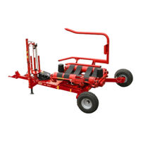
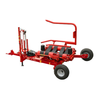
Vicon BW 2400 M Operation And Maintenance Manual (114 pages)
Brand:
Vicon
| Category:
Farm Equipment
| Size: 21 MB
Table of Contents
Table of Contents
7
General Information
9
Purpose of this Manual
9
Manufacturer and Machine Identification
10
Procedure to Request Technical Assistance
10
Glossary and Terminology
10
Attached Documentation
11
Safety Information
12
Reasonably Foreseeable Incorrect Uses
12
Residual Risks
13
Obligations of the Employer
13
General Safety Rules
14
Safety Rules about Loading and Transport Operations
14
Safety Rules about Use and Operation
15
Safety Rules about Road Circulation
16
Safety Rules about Maintenance and Adjustments
16
Safety Rules for the Environmental Impact
17
Description of Safety Signs
17
Technical Information
21
General Description of the Machine
21
Operation Cycle
23
Areas of Danger
24
Night Work
24
Technical Data
25
Allowable Slopes
27
Supplied Fittings
27
Fittings on Demand
28
Safety Devices
29
Oil-Pressure Devices
30
Electronic and Electric Devices
31
Position of Information and Safety Plates
32
Information about Handling and Loading Operations
33
Instructions for Handling and Loading
33
Packing and Unpacking
33
Loading and Unloading
33
Machine-Tractor Combination
34
How to Couple the Machine to the Tractor
35
How to Uncouple the Machine from the Tractor
37
How to Set the Height of the Drawbar
38
Assembly of Plug for the Hydraulic Control Valve
39
User Information
40
Instructions for Use and Operation
40
Description of "Lever" Controls
41
Description of "Joystick" Controls
42
Description of the "Autostop" Control Unit
43
Identification of Software Installed
43
Programming Number of Wrappings
43
Reset Counters
44
Programming Delayed Solenoid Actuation
45
Programming Delayed Solenoid Deactuation
45
Adjust Volume Acoustic Signal
46
Adjust Volume Control Key Activation
46
Reload Film Reel
46
Preparing the Machine for Use
48
Bale Wrapping Mode ("Lever" Controls)
49
Bale Wrapping Mode ("Joystick" Controls)
50
Indications to Produce Excellent Silage
53
Format Change
61
Positioning Bale Guide Cones
61
Change Reel Unwinding Ratio
62
Set Film Pre-Stretching Value
63
Change Reel Support Height
63
Road Circulation
64
How to Store the Machine at Season End
64
Putting the Machine into Service
65
Information about Adjustments
66
Instructions for Adjustments
66
Adjustment of the Pressure Control Valve
66
Adjusting the Parallelism of Bale Rotation Rollers
67
Adjusting the Tension of the Roller Transmission Chains
67
Adjustment of Film Cutting Cam
68
Adjustment of Film Cutting Unit
69
Adjustment of Film Cutting Blade
69
Adjustment of Cutting Unit Opening
70
Maintenance Information
71
Instructions for Maintenance
71
Programmed Maintenance Intervals Chart
71
Lubricant Table
72
Driving Torque Table
73
Lubrication Points Diagram
74
Changing Oil Filter Cartridge
75
Locking the Pre-Stretching Roller Hubs
75
Battery Charging Mode
76
Special Maintenance
76
Failure Information
77
Troubles, Causes, Remedies
77
Information about Replacements
80
Instructions for Part Replacement
80
How to Replace the Tyres
80
How to Replace the Safety Bolt
81
Replace the Blade of the Film Cutter
81
Machine Disposal
82
Machine Demolition
82
Annexes
84
Wiring Diagram of the Autostop Control Unit
84
(To Serial Number 163145)
86
Wiring Diagram with "Joystick" Controls
88
Wiring Diagram with "Joystick" Controls (from Serial Number 163146)
88
Wiring Diagram "Joystick" (to Serial Number163145)
90
Wiring Diagram "Joystick" (from Serial Number 163146)
91
Wiring Diagram Control Unit
92
Wiring Diagram Hydraulic Control Valve with "Joystick" Controls
93
Wiring Diagram Signal Cable for Autostop Control Unit
94
Wiring Diagram Supply Cable CAN Autostop Control Unit
95
Wiring Diagram Supply Cable
96
Wiring Diagram Signal Cable
97
Wiring Diagram Cable (3521962)
98
Wiring Diagram Cable (3521963)
99
Wiring Diagram Cable (3521971)
100
Wiring Diagram Cable (3521972)
101
Picture
102
Hydraulic System
103
Hydraulic System Diagram with "Lever" Controls
104
Hydraulic System Diagram with "Joystick" Controls
106
Hydraulic Control Valve with "Lever" Controls
108
Hydraulic Control Valve with "Joystick" Controls
109
Cutting Unit Hydraulic System Diagram
110
Advertisement
Advertisement
Related Products
Vicon BW 2100 C
Vicon BW 2400 J
Vicon Andex 1104
Vicon Andex 323
Vicon Andex 323 S
Vicon Andex 353
Vicon Andex 424 T
Vicon Andex 474 T
Vicon Andex 694 EVO
Vicon Andex 714 T Evo
Vicon Categories
Security Camera
Farm Equipment
DVR
Camera Accessories
Racks & Stands
More Vicon Manuals
Login
Sign In
OR
Sign in with Facebook
Sign in with Google
Upload manual
Upload from disk
Upload from URL