
Related Manuals for Vicon Extra 832R PRO


Summary of Contents for Vicon Extra 832R PRO
- Page 1 Extra 832R - 832CR - 835R Instruction Manual Translated from the original instruction manual Version 2012-09 Date printed 10.2012 Language Machine number KT440060 Document number 90015207EN Index number 2012-09...
- Page 2 Identification of machine So that your dealer can help you as quickly as possible, he needs to have some information about your machine. Enter your information here. Extra 832R - 832CR - 835R PRO Description 832R-CR PRO: 3.2 m (10’ 6”) Working width 835R PRO: 3.5 m (11’...
-
Page 3: Table Of Contents
Table of contents Table of contents Contents ............ Extra equipment ........167 Target group Bx equipment The meaning of the symbols High skids Quick release of knives Safety ............Roller rpm For your own safety Weights Who can operate the machine? Chain for locking the lift arms Connecting PTO shaft... -
Page 4: Contents
Contents Target group Contents This manual is intended for trained farmers and others who are qualified to work in agriculture and who are familiar with assembling equipment. For your own safety Read this instruction manual thoroughly before use and assembly. This will enable you to have optimal working conditions and to work in safety. -
Page 5: For Your Own Safety
Safety For your own Safety This chapter includes general safety instructions. In addition, each chapter in the instruction manual includes specific safety instructions safety not set out here. The safety instructions must be complied with • For your own safety. •... - Page 6 Safety Safety symbols On the machine you will find labels relating to your safety. These labels must not be removed. If the labels become illegible or detached, new labels can be ordered and affixed to the relevant areas. R model STOP STOP...
- Page 7 Safety CR model STOP STOP...
- Page 8 Safety The meaning of the Stop the tractor before working on the machine symbols Be careful! The tractor engine must ALWAYS be stopped and the ignition key removed before carrying out repairs or maintenance, cleaning, or lubricating the machine. Read and observe the instruction manual Be careful! Read and ensure you understand the instruction manual before the machine is used.
- Page 9 Safety Risk from loose chippings Keep a safe distance from the machine. Do not allow any persons near the machine when it is working. If the guard is damaged, it must be replaced. Danger of being crushed by the machine's cutting unit The safety valve must always be closed during repair or maintenance operations on the machine's cutting unit.
- Page 10 Safety Ensure no clothing/body parts get caught in the machine No work may be carried out on the machine's rotors or cutterbar until the machine has stopped rotating. The tractor engine must be stopped, the ignition key removed and the handbrake applied. Ensure no clothing/body parts get caught in the V belt transmission Guards may not be removed or opened until the machine has stopped...
-
Page 11: Who Can Operate The Machine
Safety Who can operate Operators of this machine should only be trained farmers and others who are qualified to work in agriculture and who are familiar with the machine? assembling equipment. Untrained or unauthorised persons must not use this machine. Connecting Correct attachment of the machine The machine must be correctly attached, in accordance with the... -
Page 12: Load Capacity
Safety Only connect hydraulics when the system is depressurised You should only connect the hydraulic hoses to the tractor's hydraulics when the hydraulic system on both the tractor and the machine is depressurised. There is a risk that the machine will move accidentally. Unintentional movement of the machine may result in serious injuries. -
Page 13: Transport On Public Roads
Safety Transport on Ensure that the machine meets the Road Traffic Act's require- ments concerning its condition public roads When driving on public roads, the machine must comply with the Road Traffic Act's current requirements. This ensures your safety and that of other road users. Failure to meet the requirements can result in accidents. -
Page 14: Use
Safety The operator should receive careful instructions before using the machine The machine should only be used if the operator has been given thorough instructions. Thorough machine instruction allows safe usage. 95-002-1 fr Insufficient training may lead to incorrect usage of the machine and accidents. - Page 15 Safety Check the surrounding area before starting to use the machine Before driving and using the machine the surrounding area should be checked. This prevents persons and animals in the vicinity from being harmed. If the surrounding area is not checked, it may result in serious injuries to persons or animals.
-
Page 16: Disconnection
Safety Disconnection Increased risk of injury when disconnecting There is an increased risk of injury when disengaging the machine from the tractor. Paying full attention to this will protect your own and others' safety. 95-031 fr Failure to follow the abovementioned point may result in serious injuries. -
Page 17: Maintenance
Safety Maintenance Comply with the service and maintenance intervals given in the instructions Comply with the intervals for service and maintenance as given in the instructions. By complying with the maintenance intervals you ensure that the machine will operate without malfunctions and provide maximum protection for the environment. - Page 18 Safety Be careful when cleaning with high pressure cleaning equipment Only use low pressure cleaning equipment to clean bearings, hydraulic hoses, plastic components, electrical control boxes and electrical equipment. Using low water pressure to clean will protect the sensitive equipment on the machine.
-
Page 19: Further Safety Instructions
Safety Further safety Follow the instructions when working on the machine The machine safety instructions should always be complied with. instructions This will protect you and others from injury. Failure to follow the safety instructions may result in serious injuries. In addition to the safety instructions the following should be complied with: 95-005 fr... -
Page 20: About The Machine
About the machine About the machine This chapter includes general information about your machine. In addition, the following information is included: • The machine's field of application. • The machine characteristics. • View of the machine. • Technical data. The machine's 832R - 832 CR - 835R PRO is a towed swather intended for swath laying common grass and corn crops. -
Page 21: Machine Characteristics
About the machine Machine Description of the machine 832R - 832 CR - 835R PRO is a towed swather: characteristics • The R model can only operate on the right-hand side of the tractor. • The CR model can operate on both sides of the tractor. The machine is towed behind the tractor via a drawbar which is coupled to the tractor's lift arms. -
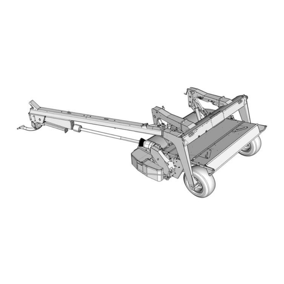
Page 22: Synopsis
About the machine Synopsis R model Hydraulic cylinder Cutting unit Swivel gear Spring Drawbar Support leg Lighting kit Main frame Guard Swivel hitch PTO shaft Main gear... - Page 23 About the machine CR model Hydraulic cylinder Drawbar Main frame Cutting unit Centre gear Swivel gear Support leg Guard Spring Swivel hitch PTO shaft Main gear Lighting kit...
-
Page 24: Technical Data
About the machine Technical data Machine dimensions R model... - Page 25 About the machine Dim. Unit 832R PRO 835R PRO mm (’-’’) 5650 (18' 6'') 5650 (18' 6'') mm (’-’’) 5600 (18' 4'') 5600 (18' 4'') mm (’-’’) 350 (1' 2'') 350 (1' 2'') mm (’-’’) 3050 (10') 3050 (10') mm (’-’’) 1400 (4' 7'') 1400 (4' 7'') mm (’-’’)
- Page 26 About the machine CR model...
- Page 27 About the machine Dim. Unit 832CR PRO mm (’-’’) 7225 (23' 8'') mm (’-’’) 6250 (20' 6'') mm (’-’’) 350 (1' 2'') mm (’-’’) 6000 (19' 8'') mm (’-’’) 1425 (4' 8'') mm (’-’’) 3200 (10' 6'') mm (’-’’) 2400 (7' 10'') mm (’-’’) 675 (2' 2'') mm (’-’’)
-
Page 28: Tractor Requirements
About the machine Machine specifica- tions Unit 832R PRO 832CR PRO 835R PRO Own weight kg (lb) 1960 (4322) 2120 (4675) 2060 (4542) PTO (power take off) 540/1000 540/1000 540/1000 power requirement, minimum kw (hp) 60 (80) 60 (80) 70 (90) number of cutting discs parts number of knives... -
Page 29: Preparation
Preparation Preparing the Preparation The machine is divided into its main components for transport to the user. The machine must be assembled in accordance with the specific machine assembly instructions delivered with each machine. The following chapter is for initial assembly and shortening of the PTO shaft, etc. - Page 30 Preparation The swivel gear's rpm can also be checked by observing the gear's pivot joint. Check the swivel gear in the following way: Observe the gear's profile in the middle of the swivel gear. • If the swivel gear's profile on the lower part of the swivel gear is wide, the machine should be run at a rotational speed of 1000 rpm.
- Page 31 Preparation Remove the bolts shown on both sides of the transmission. Bracket Remove the bracket. Bolt Force the corners of the lock plate away from the bolt heads. Bolt Remove the bolts shown on both sides of the transmission. ...
- Page 32 Preparation Remove the air release plug and the oilplug and switch them over. Air release plug Remove the adapter for the PTO shaft. Oilplug Adapter Rotate the transmission 180 degrees.
- Page 33 Preparation Fit the transmission. Bolt Do not forget the lock plate. Fit the bolts on both sides of the transmission Tighten all bolts to a torque of 225 Nm (165 ft/lb). Fit the adapter. 225 Nm 165 ft/lb Adapter Lock plate...
-
Page 34: Assembly - Attachment
Assembly - attachment Assembly - attachment Coupling a tractor and a machine There is an increased risk of injury when attaching the machine to the tractor. Attention to the task will ensure your safety and that of others. Failure to follow the safety instructions may result in serious injuries. Therefore, when connecting the machine and the tractor you should: •... -
Page 35: Attachment Of The Tractor
Assembly - attachment Attachment of the Lock the tractor's lift arms Lock the tractor's lift arms at the correct height. tractor If the lift arms are at the correct height,it will prevent damage to the PTO shaft and injury to persons in the vicinity. Lowering or raising the lift arms can lead to injury and can damage the PTO shaft. - Page 36 Assembly - attachment Connecting the machine When connecting the machine there is an increased risk of injury. Attention to the task will ensure your safety and that of others. Failure to follow the safety instructions may result in serious injuries. Secure the attachment with the locking pin The attachment must be secured to the machine with the locking pin.
- Page 37 Assembly - attachment Lock the lift arms with a chain* or solid bar between the lift arms Chain* or solid bar and the highest point. * Optional equipment. »Extra equipment« Page 167 Attach the PTO shaft to the tractor. When checking and shortening the PTO shaft, refer to the manufac- turer's instructions, delivered with the PTO shaft.
-
Page 38: Hydraulic
Assembly - attachment Hydraulic Safety Only connect hydraulics when the system is depressurised You should only connect the hydraulic hoses to the tractor's hydraulics when the hydraulic system on both the tractor and the machine is depressurised. There is a risk that the machine will move accidentally. Unintentional movement of the machine may result in serious injuries. -
Page 39: Connection
Assembly - attachment Connection Hydraulic connection Drawbar The tractor must be fitted with 2 sets of double acting hydraulic outlets, which are connected as follows: Hydraulic hose for: Function right Drawbar left Cutting unit down When connecting the hydraulic hoses you should check that: Cutting unit •... -
Page 40: First Start-Up Of Machine
Assembly - attachment First start-up of The initial test drive of the machine is important When the machine is connected to the tractor for the first time it must machine be test driven. Attention to the task will ensure your safety and that of others. Failure to follow the safety instructions may result in serious injuries. - Page 41 Assembly - attachment Checking the cutting unit Equalising the hydraulic system After a prolonged period without use with the cutting unit raised, there is a risk that the machine's cutting unit may sink unevenly in the machine's hydraulic cylinder. This means that the cutting unit is not parallel with the machine's main frame.
- Page 42 Assembly - attachment Friction clutch Safety in connection with maintenance work on the machine When working on the machine the tractor must be stopped and secured. This prevents the PTO shaft from suddenly starting to rotate. If the tractor and the PTO shaft have not been connected following the instructions, serious accidents causing damage to limbs can occur.
- Page 43 Assembly - attachment CR model Use a suitable tool to remove the bolts. Remove the cover. Bolts Bolt Tighten all bolts on the friction clutch. Bolt R and CR model Remove the linchpins shown here. Open the first guard.
- Page 44 Assembly - attachment Suspend the guard in the chain as shown. Block the cutter bar by placing a wooden block between the two cutting discs. Start the tractor and connect the tractor's PTO outlet. Wooden block Let the friction clutch rotate freely for approx. 5 seconds at the lowest possible speed, until it is warm to the touch.
- Page 45 Assembly - attachment R model Bolt Remove the PTO shaft on the main gear. Loosen all the bolts on the friction clutch. Fit and tighten the PTO shaft fully on the drawbar. Close the guard. Guard CR model Bolt ...
- Page 46 Assembly - attachment Fit the cover. Fit the bolts. Bolts C and CR model Remove the wooden block from the cutterbar. Wooden block Close the front guard. Fit the linchpins shown here.
-
Page 47: Machine In The Transport Position
Assembly - attachment Machine in the Check the surrounding area before starting to use machine Before driving and using the machine the surrounding area should be transport position checked. This prevents persons and animals in the vicinity from being harmed. Valve If the surrounding area is not checked, it may result in serious injuries to persons or animals. - Page 48 Assembly - attachment Guard Right-hand side Lift the guard up as shown. Fit the linchpin as shown. Linchpin...
- Page 49 Assembly - attachment Left-hand side R model Swivel the guard round as shown. Take hold of the bar and lift the guard up as shown. Secure the guard with the linchpin. If the side guard is in the transport position, the machine must not be started.
- Page 50 Assembly - attachment CR model Swivel the guard round as shown. Tilt the whole guard up as shown. Fit the linchpin. If the side guard is in the transport position, the machine must not be started.
-
Page 51: Transport On Public Roads
Transport on public roads Safety Transport on public roads Read the safety instructions carefully before driving on public roads Before driving on public roads, you must read the safety instructions carefully. This will ensure that dangerous situations and accidents are avoided. Lack of information can cause accidents. -
Page 52: Checking The Machine
Transport on public roads Checking the Before travelling on the road the machine should be checked according to this check list: machine Is the machine in the transport position? Is the cutting unit lifted all the way up? ... -
Page 53: Operation
Operation Safety Operation Read the safety instructions before using the machine Before using the machine, the operator should read the safety instruc- tions carefully. »Safety« Page 5 Attention to the task will ensure your safety and that of others. Failure to follow the instructions may result in serious injuries. -
Page 54: Operation
Operation Operation Safety The operator should receive careful instructions before using the machine The machine should only be used if the operator has been given thorough instructions. Thorough machine instruction allows safe usage. Insufficient training may lead to incorrect usage of the machine and accidents. - Page 55 Operation Check that the mechanical safety valve is open. Valve Carefully connect the tractor's PTO shaft. Carefully increase the speed of the PTO shaft to 540/1000 rpm. »Number of revolutions on the PTO outlet« Page 30 ...
- Page 56 Operation Setting Rollers Rpm for the rollers is 900 rpm as standard. The machine can be fitted with a pulley as extra equipment so that the rpm of the rollers is 1200 rpm. Type of crop Rollers Diameter Pulley on the transmission Normal grass crops as well as alfalfa and clover without using Bx 225 mm (8 ’’)
- Page 57 Operation Completely loosen the bolt on the spring. Bolt Remove the V-belts. V-belt Bolt Remove the bolt for the pulley.
- Page 58 Operation Remove the pulley. Pulley Fit the new pulley. V-belt Fit the V-belts. Tighten the springs to the measurement shown. Fit the guard. Bolt 75 mm (3”)
- Page 59 Operation Roller pressure The pressure of the rollers on the crop depends on the type and nature of the crop: • when cutting grassy crops, the roller pressure should be increased. • When cutting clover and other leafy crops, the roller pressure should be reduced.
- Page 60 Operation Changing the roller pressure The setting for the springs must be exactly the same on both sides of the machine. The roller pressure is adjusted in the following way: Counter nut Left-hand side: Use the appropriate tools to loosen the counter nut shown, which is located close to the springs.
- Page 61 Operation Tighten and secure the counter nut on the spring after the final Counter nut adjustment. The setting for the springs must be exactly the same on both sides of the machine.
- Page 62 Operation The setting for the springs must be exactly the same on both sides of the machine. The roller pressure is adjusted in the following way: Right-hand side: Use the appropriate tools to loosen the counter nut shown, which is located close to the springs.
- Page 63 Operation Distance between the Reducing the distance between the rollers rollers The distance between the rollers is reduced in the following way: Loosen the counter nut shown. Reduce the distance between the rollers by turning the nuts shown.
- Page 64 Operation The recommended distance between the rollers is 3 mm ( ’’). 3 mm ( ’’) The distance between the rollers is checked in the following way: It is recommended that the check be carried out by two people. Place a 3 mm ( ’’) spacer in between the rollers approx.
- Page 65 Operation Increasing the distance between the rollers The distance between the rollers is increased in the following way: Loosen the counter nut shown. Increase the distance between the rollers by turning the nuts shown.
- Page 66 Operation The recommended distance between the rollers is 3 mm ( ’’). 3 mm ( ’’) The distance between the rollers is checked in the following way: It is recommended that the check be carried out by two people. Place a 3 mm ( ’’) spacer in between the rollers approx.
- Page 67 Operation Deflector plates The machine is fitted with 2 deflector plates, making it possible to adjust the cutting swath to suit the following chopper. Ring nut The cutting swath should be as broad and even as possible. Use a suitable tool and loosen the ring nut. ...
- Page 68 Operation Stubble height The machine has variable settings for stubble height. Stubble height is adjusted in the following way: Turn the left handle. • When the handle is turned clockwise, stubble height is reduced . • When the handle is turned anti clockwise, stubble height is increased.
- Page 69 Operation Balancing the cutting The balancing of the machine's cutting unit should be adjusted so that unit the downward pressure on the machine's cutting unit is about 40-60 kg (90-130 lb). The balancing of the cutting unit is adjusted in the following way: ...
- Page 70 Operation Adjust the cutting unit's downward pressure for both springs. Secure the counter nuts with the springs on both sides of the machine. Check by lifting the cutting unit by hand, gripping both sides of the cutting unit in the places shown. When checking the suspension, position yourself in front of the cutting unit and lift the cutting unit up as shown.
- Page 71 Operation Working in the field Check the surrounding area before starting to use the machine Before driving and using the machine the surrounding area should be checked. This prevents persons and animals in the vicinity from being harmed. If the surrounding area is not checked, it may result in serious injuries to persons or animals.
- Page 72 Operation Check that the hydraulic mechanical safety valve is open. Valve Connect the tractor's PTO outlet. Carefully increase the speed on the PTO shaft to 540/1000 rpm. »Number of revolutions on the PTO outlet« Page 30 ...
- Page 73 Operation Activate the tractor hydraulics and lower the cutting unit of the machine to its working position. Activate the tractor hydraulics until the hydraulic cylinders on the cutting unit are fully extended to their maximum length. Find a suitable driving speed for the tractor and cut the 2nd swath.
- Page 74 Operation CR model The CR model is operated in the following way: Check that all guards on the machine are folded out and correctly positioned. Valve Check that the hydraulic mechanical safety valve is open. Connect the tractor's PTO outlet. ...
- Page 75 Operation Activate the tractor hydraulics and turn the machine's drawbar to the left side of the tractor. Activate the tractor hydraulics and lower the cutting unit of the machine to its working position. Activate the tractor hydraulics until the hydraulic cylinders on the cutting unit are fully extended to their maximum length.
- Page 76 Operation Activate the tractor hydraulics and lower the cutting unit of the machine to its working position. Activate the tractor hydraulics until the hydraulic cylinders on the cutting unit are fully extended to their maximum length. Find a suitable driving speed for the tractor and cut the 2nd swath.
-
Page 77: Before Cleaning
Cleaning Before cleaning Cleaning Higher risk when cleaning the equipment When cleaning, there is an increased risk of injury. Paying attention when carrying out cleaning work will ensure your safety and that of others. Failure to follow the safety instructions may cause serious injuries. Therefore, do the following before cleaning: •... -
Page 78: Cleaning
Cleaning Cleaning Use the correct cleaning agents Use only PH neutral cleaning agents when cleaning the machine. PH neutral cleaning agents give your machine maximum protection. Cleaning agents with either high or low PH value can be corrode plastic, rubber and painted surfaces. •... -
Page 79: Parking And Storage
Parking and Storage Before storage Parking and Storage At the end of the season, the machine should be prepared for storage: Check and tighten all bolts. »Torque moment« Page 177 Repair any damaged components. Replace any defective components. ... - Page 80 Parking and Storage Hydraulic Only disconnect hydraulics when the system is depressurised You should only disconnect the hydraulic hoses from the tractor's hydraulics if the hydraulic systems on both tractor and machine are depressurised. There is a risk that the machine will move accidentally. Unintentional movement of the machine may result in serious injuries.
-
Page 81: Storage
Parking and Storage Storage At the end of the season, the machine should be prepared for storage. Carry out the following: • Clean the machine thoroughly. »Cleaning« Page 77 • Change the oil in all the machine's transmissions. »Lubricants« Page 177 •... -
Page 82: Maintenance
Maintenance For your own Maintenance Comply with the service and maintenance intervals given in the instructions safety Comply with the intervals for service and maintenance as given in the instructions. By complying with the maintenance intervals you ensure that the machine will operate without malfunctions and provide maximum protection for the environment. -
Page 83: General Instructions
Maintenance General instruc- These instructions concern general maintenance work. Specific maintenance work procedures for each machine will be described tions later. When performing any maintenance work the machine must be secured in the transport position. If the work position is necessary for performing maintenance work, you will find appropriate instructions to cover this. - Page 84 Maintenance Maintenance intervals • Hydraulic hoses, every 4 years • Cutting disc after 1 hour of use • • Cutting disc • • • • Universal joint • Knife after 1 hour of use • • Knives • • • PTO shaft •...
- Page 85 Maintenance Gearbox - R model: • • Swivel gear • • • • • • Main gear • • • • Gearbox - CR model: • • Swivel gear • • • • • • Centre gear • • • •...
- Page 86 Maintenance • • Wheel bolts • • • • Accumulator* • • *May only be carried out by authorised service personnel.
- Page 87 Maintenance Safety in connection with maintenance work on the machine When working on the machine the tractor must be stopped and secured. This prevents the PTO shaft from suddenly starting to rotate. If the tractor and the PTO shaft have not been connected following the instructions, serious accidents causing damage to limbs can occur.
-
Page 88: Lubrication
Maintenance Lubrication Every 40 hours Drawbar Press the nozzle of the grease gun over the grease nipple. Pump the grease gun once or twice (max.). »Maintenance intervals« Page 84 »Lubricants« Page 177 58.237.000 Press the nozzle of the grease gun over the grease nipple. ... - Page 89 Maintenance Swivel gear Press the nozzle of the grease gun over the grease nipple. Pump the grease gun once or twice (max.). »Maintenance intervals« Page 84 »Lubricants« Page 177 58.237.000 Cutting unit Locate the grease nipple on both sides of the machine. ...
- Page 90 Maintenance Every 100 hours of PTO shaft Find the hole in the band and turn the PTO shaft until the grease nipple is visible. Press the nozzle of the grease gun onto the grease nipple. Pump the grease gun once or twice (max.). ...
- Page 91 Maintenance CR model Turn the PTO shaft until the grease nipple is visible. Press the nozzle of the grease gun over the grease nipple. 58.237.000 Pump the grease gun once or twice (max.). »Maintenance intervals« Page 84 ...
- Page 92 Maintenance As required Connecting links, etc. Right-hand side Press the nozzle of the grease gun over the grease nipple. Pump the grease gun once or twice (max.). »Maintenance intervals« Page 84 »Lubricants« Page 177 58.237.000 58.237.000 ...
- Page 93 Maintenance Left-hand side Press the nozzle of the grease gun onto the grease nipple. Pump the grease gun once or twice (max.). »Maintenance intervals« Page 84 »Lubricants« Page 177 58.237.000 58.237.000 Spindle with springs Press the nozzle of the grease gun onto the grease nipple. ...
-
Page 94: Service - Check
Maintenance Service - check Safety concerning maintenance work on the cutting unit When working on the cutting unit the tractor must be stopped and secured. This prevents the machine from suddenly starting to rotate. If the tractor and the PTO shaft have not been connected following the instructions serious accidents causing damage to limbs can occur. - Page 95 Maintenance Inspection - oil service Every day »Maintenance intervals« Page 84 The oil level for the cutterbar is checked as follows: Place the machine on a level surface. Remove the linchpins shown here. Open the first guard. ...
- Page 96 Maintenance Close the mechanical safety valve. Valve Check that the cutterbar is horizontal in the direction shown using a spirit level or similar tool. If the cutterbar is not horizontal, carry out the following: Raise or lower the tractor's lift arms until the cutterbar is horizontal.
- Page 97 Maintenance Locate the oilplug on the left side of the cutterbar and remove it. • With warm oil: Wait approximately 3 minutes • With cold oil: Wait approximately 15 minutes. Check the oil level as shown and refill if necessary. •...
- Page 98 Maintenance Adjust the tractor's lift arms to the height shown. 620 - 630 mm (24 ’’ - 24 ’’) Chain or solid bar Lock the lift arms with a chain or solid bar between the lift arms and the highest point.
- Page 99 Maintenance Gearbox Pay attention when carrying out oil change Use barrier cream or protective gloves when changing oil. It will protect your hands against skin injuries. Direct contact with the oil could lead to serious skin injuries. Use the correct oil type Always use the correct oil type for the transmission.
- Page 100 Maintenance CR model Dipstick The oil level is checked as follows: Remove the dipstick. Check that the oil level is up to the “max” indication on the dipstick. The oil level on the main gear must always be between “min.” and “max.”...
- Page 101 Maintenance Centre gear Checking the oil level Every 80 hours of use CR model only Oilplug 1 »Maintenance intervals« Page 84 The oil level is checked as follows: Remove oilplug 2. Check that the oil reaches the edge of the hole for oilplug 2. ...
- Page 102 Maintenance Swivel gear Checking the oil level Every 80 hours of use »Maintenance intervals« Page 84 The oil level is checked as follows: Oilplug 1 The upper part of the swivel hitch Remove oilplug 2. Check that the oil is filled all the way up to the hole. ...
- Page 103 Maintenance Rollers Pay attention when carrying out oil change Use barrier cream or protective gloves when changing oil. It will protect your hands against skin injuries. Direct contact with the oil could lead to serious skin injuries. Use the correct oil type Always use the correct oil type for the transmission.
- Page 104 Maintenance Every month Oilplug The oil level is checked as follows: Remove the oilplug. Check that the oil level reaches the hole. When topping up, fill the oil through the hole for the oilplug. • The correct oil level is reached when the oil reaches the edge of the hole for the oilplug.
- Page 105 Maintenance Knives Safety concerning maintenance work on the cutting unit When working on the cutting unit the tractor must be stopped and secured. This prevents the machine from suddenly starting to rotate. If the tractor and the PTO shaft have not been connected following the instructions serious accidents causing damage to limbs can occur.
- Page 106 Maintenance Activate the tractor hydraulics and raise the machine's cutterbar fully. Valve Close the mechanical safety valve. Turn the cutting discs by hand until the damaged knife is in the 95 Nm +/- 5 position shown. 70 ft/lb. +/- 3 ...
- Page 107 Maintenance Knife If the machine is fitted with knife quick release*, the same requirement applies for bolt wear. »Knives« Page 146 * Extra equipment »Quick release of knives« Page 168 Min. 16 mm ( ”) Spring Valve Open the mechanical safety valve. ...
- Page 108 Maintenance Cutting disc Safety concerning maintenance work on the cutting unit When working on the cutting unit the tractor must be stopped and secured. This prevents the machine from suddenly starting to rotate. If the tractor and the PTO shaft have not been connected following the instructions serious accidents causing damage to limbs can occur.
- Page 109 Maintenance Activate the tractor hydraulics and raise the machine's cutterbar fully. Valve Close the mechanical safety valve. 80 Nm +/- 5 59 ft/lb. +/- 3 Inspect the condition of the cutting discs for deformities and cracks. Use a suitable tool and tighten the cutting disc to a torque of 80 Nm (59 ft/lb).
- Page 110 Maintenance Activate the tractor hydraulics and lower the cutting unit of the machine. Close the front guard. Fit the linchpins shown here.
- Page 111 Maintenance Cone Safety concerning maintenance work on the cutting unit When working on the cutting unit the tractor must be stopped and secured. This prevents the machine from suddenly starting to rotate. If the tractor and the PTO shaft have not been connected following the instructions serious accidents causing damage to limbs can occur.
- Page 112 Maintenance Close the mechanical safety valve. Valve Remove dirt from the cones on both sides of the machine. Valve Open the mechanical safety valve. Activate the tractor hydraulics and lower the cutting unit of the machine.
- Page 113 Maintenance Close the front guard. Fit the linchpin. Internal inspection Every season »Maintenance intervals« Page 84 An internal check of the cones is carried out in the following way: Remove the linchpins shown here. Open the first guard. ...
- Page 114 Maintenance Close the mechanical safety valve. Valve Use a suitable tool and remove the guard around the cutterbar's transmission. Guard Remove the top cover from the cone. Clean the inside of the cone. Fit the cone's top cover. Top cover ...
- Page 115 Maintenance Remove the top cover on the cone on the opposite side of the transmission. Clean the inside of the cone. Fit the cone's top cover. Top cover Valve Open the mechanical safety valve. Activate the tractor hydraulics and lower the cutting unit of the machine.
- Page 116 Maintenance Universal joint Safety concerning maintenance work on the cutting unit When working on the cutting unit the tractor must be stopped and secured. This prevents the machine from suddenly starting to rotate. If the tractor and the PTO shaft have not been connected following the instructions serious accidents causing damage to limbs can occur.
- Page 117 Maintenance Close the mechanical safety valve. Valve Use a suitable tool and remove the guard around the PTO shaft between the transmission and the cutterbar. Guard Remove the top cover from the cone. Top cover...
- Page 118 Maintenance Inspect both universal joints for wear. Universal joint Check for broken or loose bolts. Bolts Replace the broken bolts. Apply Loctite 242 to the bolts. Fit the bolts and tighten to the torque shown. 79 Nm 58 ft/lb Loctite 242...
- Page 119 Maintenance If there are loose bolts the following procedure should be followed: Remove and clean the bolts. Bolts Apply Loctite 242 or a similar product to all bolts. Fit the bolts and tighten to the torque shown. 79 Nm 58 ft/lb Loctite 242...
- Page 120 Maintenance Open the mechanical safety valve. Valve Activate the tractor hydraulics and lower the cutting unit of the machine. Close the front guard. Fit the linchpin.
- Page 121 Maintenance Stone guard and Safety concerning maintenance work on the cutting unit counter knife When working on the cutting unit the tractor must be stopped and secured. This prevents the machine from suddenly starting to rotate. If the tractor and the PTO shaft have not been connected following the instructions serious accidents causing damage to limbs can occur.
- Page 122 Maintenance Carry out a visual inspection of the machine's stone guard and counter knife for wear. Stone guards and counter knives with visible holes caused by heavy wear must be replaced immediately. »Stone guard and counter knife« Page 157 ...
- Page 123 Maintenance Rollers Safety concerning maintenance work on the cutting unit When working on the cutting unit the tractor must be stopped and secured. This prevents the machine from suddenly starting to rotate. If the tractor and the PTO shaft have not been connected following the instructions serious accidents causing damage to limbs can occur.
- Page 124 Maintenance Inspect the rollers for lodged foreign bodies. Rollers Valve Open the mechanical safety valve. Activate the tractor hydraulics and lower the cutting unit of the machine.
- Page 125 Maintenance Transmission After 10 hours of use Thereafter, every 40 hours »Maintenance intervals« Page 84 of use The V-belts on the rotor must be regularly checked. The V-belts for the rotor transmission are checked as follows: Activate the tractor hydraulics and lower the cutting unit of the machine.
- Page 126 Maintenance Use a tape measure or similar to measure the springs as shown. V-belt The springs are tightened with a bolt to the measurement shown. A new machine or a newly fitted V-belt should be checked after a few hours use.
- Page 127 Maintenance Friction clutch Safety concerning maintenance work on the transmission When working on the transmission the tractor must be stopped and secured. This prevents the machine from suddenly starting to rotate. If the tractor and the PTO shaft have not been connected following the instructions serious accidents causing damage to limbs can occur.
- Page 128 Maintenance CR model Use a suitable tool to remove the bolts. Remove the cover. Bolts Bolt Tighten all bolts on the friction clutch. Bolt R and CR model Remove the linchpins shown here. Open the first guard.
- Page 129 Maintenance Suspend the guard in the chain as shown. Block the cutter bar by placing a wooden block between the two cutting discs. Start the tractor and connect the tractor's PTO outlet. Wooden block Let the friction clutch rotate freely for approx. 5 seconds at the lowest possible speed, until it is warm to the touch.
- Page 130 Maintenance R model Bolt Remove the PTO shaft on the main gear. Loosen all the bolts on the friction clutch. Fit and tighten the PTO shaft fully on the drawbar. Close the guard. Guard CR model Bolt ...
- Page 131 Maintenance Fit the cover. Fit the bolts. Bolts R and CR model Remove the wooden block from the cutterbar. Wooden block Close the front guard. Fit the linchpins shown here.
- Page 132 Maintenance Accumulator Very high amount of accumulated pressure in the accumulator Do not attempt to take the accumulator apart. The accumulator contains very high accumulated pressure and may only be taken apart by authorised persons. Attempting to take the accumulator apart can lead to serious or fatal injury.
-
Page 133: Replacement
Maintenance Replacement Safety concerning maintenance work on the cutting unit When working on the cutting unit the tractor must be stopped and secured. This prevents the machine from suddenly starting to rotate. If the tractor and the PTO shaft have not been connected following the instructions serious accidents causing damage to limbs can occur. - Page 134 Maintenance Remove the linchpins shown here. Open the first guard. Suspend the guard in the chain as shown. Activate the tractor hydraulics and raise the machine's cutterbar fully. Valve Close the mechanical safety valve.
- Page 135 Maintenance Locate the drain plug on the left side of the cutterbar and remove it. Let the oil flow into a suitable container. Allow the last of the oil to drip out of the cutterbar for approx. 10 - 15 minutes.
- Page 136 Maintenance If the cutterbar is not horizontal, carry out the following: Raise or lower the tractor's lift arms until the cutterbar is horizontal. Remove the oilplug. Fill up with the new oil until the oil level is as shown. Model: Litre Pints (US)
- Page 137 Maintenance Activate the tractor hydraulics and lower the cutting unit of the machine. Close the front guard. Fit the linchpin. Adjust the tractor's lift arms to the height shown. 620 - 630 mm (24 ’’ - 24 ’’) Chain* or solid bar ...
- Page 138 Maintenance Gearbox Pay attention when carrying out oil change Use barrier cream or protective gloves when changing oil. It will protect your hands against skin injuries. Direct contact with the oil could lead to serious skin injuries. Use the correct oil type Always use the correct oil type for the transmission.
- Page 139 Maintenance Use a suitable tool to remove the oilplug. Let the oil flow into a suitable container. Allow the last of the oil to drip out of the transmission for approx. 10 - 15 minutes. Fit the oilplug and tighten it. Oilplug Dipstick ...
- Page 140 Maintenance CR model The oil is changed as follows: Remove the guard. Bolt Use a suitable tool to remove the oilplug. Let the oil flow into a suitable container. Allow the last of the oil to drip out of the transmission for approx. 10 - 15 minutes.
- Page 141 Maintenance Fit the guard. Bolt...
- Page 142 Maintenance Centre gear Changing oil After 10 hours of use Thereafter, every season CR model only »Maintenance intervals« Page 84 Oil amount when changing oil: Litre Pints (US) Pints (Imp.) (approx.) (approx.) (approx.) The oil is changed as follows: ...
- Page 143 Maintenance Swivel gear Changing oil After 10 hours of use Thereafter, every season Oilplug 1 The upper part of the swivel hitch Oilplug 2 Oil amount when changing oil: Litre Pints (US) Pints (Imp.) (approx.) (approx.) (approx.) The oil is changed as follows: ...
- Page 144 Maintenance Rollers Pay attention when carrying out oil change Use barrier cream or protective gloves when changing oil. It will protect your hands against skin injuries. Direct contact with the oil could lead to serious skin injuries. Use the correct oil type Always use the correct oil type for the transmission.
- Page 145 Maintenance After 10 hours of use Thereafter, every season Oil amount when changing oil: Litre Pints (US) Pints (Imp.) (approx.) (approx.) (approx.) 0.75 Oilplug 3 Replace the oil as follows: Remove oilplug 4. Let the oil flow into a suitable container. ...
- Page 146 Maintenance Knives Safety concerning maintenance work on the cutting unit When working on the cutting unit the tractor must be stopped and secured. This prevents the machine from suddenly starting to rotate. If the tractor and the PTO shaft have not been connected following the instructions serious accidents causing damage to limbs can occur.
- Page 147 Maintenance Activate the tractor hydraulics and raise the machine's cutterbar fully. Valve Close the mechanical safety valve. Turn the cutting discs by hand until the damaged knife is in the 95 Nm +/- 5 position shown. 70 ft/lb. +/- 3 ...
- Page 148 Maintenance Knife If the machine is fitted with knife quick release*, the same requirement applies for bolt wear. »Knives« Page 105 * Extra equipment »Quick release of knives« Page 168 Min. 16 mm ( ”) Spring Valve Open the mechanical safety valve. ...
- Page 149 Maintenance Cutting disc Safety concerning maintenance work on the cutting unit When working on the cutting unit the tractor must be stopped and secured. This prevents the machine from suddenly starting to rotate. If the tractor and the PTO shaft have not been connected following the instructions serious accidents causing damage to limbs can occur.
- Page 150 Maintenance Activate the tractor hydraulics and raise the machine's cutterbar fully. Valve Close the mechanical safety valve. Use a suitable tool to remove the cutting disc. Bolt Remove the bolt and knife from the cutting disc.
- Page 151 Maintenance Fit the knife and bolt on the new cutting disc. Tighten up the bolt with a torque wrench to the torque shown. 95 Nm +/- 5 70 ft/lb. +/- 3 Bolt Bolt 80 Nm +/- 5 59 ft/lb. +/- 3 Loctite 242 ...
- Page 152 Maintenance Activate the tractor hydraulics and lower the cutting unit of the machine. Close the front guard. Fit the linchpin.
- Page 153 Maintenance Universal joint Safety concerning maintenance work on the cutting unit When working on the cutting unit the tractor must be stopped and secured. This prevents the machine from suddenly starting to rotate. If the tractor and the PTO shaft have not been connected following the instructions serious accidents causing damage to limbs can occur.
- Page 154 Maintenance Activate the tractor hydraulics and raise the machine's cutterbar fully. Valve Close the mechanical safety valve. Use a suitable tool and remove the guard around the PTO shaft between the transmission and the cutterbar. Guard Remove the top cover from the cone. Top cover...
- Page 155 Maintenance PTO shaft Bolts Remove the bolts and replace the PTO shaft. Clean the bolts. Apply Loctite 242 or a similar product to all bolts. Fit the bolts and tighten to the torque shown. 79 Nm 58 ft/lb Loctite 242 ...
- Page 156 Maintenance Open the mechanical safety valve. Valve Activate the tractor hydraulics and lower the cutting unit of the machine. Close the front guard. Fit the linchpin.
- Page 157 Maintenance Stone guard and Safety concerning maintenance work on the cutting unit counter knife When working on the cutting unit the tractor must be stopped and secured. This prevents the machine from suddenly starting to rotate. If the tractor and the PTO shaft have not been connected following the instructions serious accidents causing damage to limbs can occur.
- Page 158 Maintenance Remove the worn stone guard and counter knife. Fit the new stone guard and counter knife. Stone guards and counter knives with visible holes caused by heavy wear must be replaced immediately. Remove the support. Valve ...
- Page 159 Maintenance Rollers Safety concerning maintenance work on the cutting unit When working on the cutting unit the tractor must be stopped and secured. This prevents the machine from suddenly starting to rotate. If the tractor and the PTO shaft have not been connected following the instructions serious accidents causing damage to limbs can occur.
- Page 160 Maintenance Remove the guard around the transmission. Bolt Bolt Completely loosen the bolt on the spring. Remove the V-belts. Fit the new V-belts. V-belt...
- Page 161 Maintenance Tighten the springs to the measurement shown. V-belt Bolt 75 mm (3”) Fit the guard around the transmission. Bolt...
- Page 162 Maintenance Friction clutch Safety concerning maintenance work on the transmission When working on the transmission the tractor must be stopped and secured. This prevents the machine from suddenly starting to rotate. If the tractor and the PTO shaft have not been connected following the instructions serious accidents causing damage to limbs can occur.
- Page 163 Maintenance Use a screwdriver or similar pointed tool to force the circlip out of Use pointed tool the friction clutch. Take the friction clutch apart and replace the friction discs. Assemble and fit the friction clutch. Fit the circlip. Circlip Bolt ...
- Page 164 Maintenance CR model Use a suitable tool to remove the bolts. Remove the cover. Bolts Bolt Remove the bolts and pull the friction clutch away from the shaft. Bolt Bolt Tighten all bolts on the friction clutch.
- Page 165 Maintenance Use a screwdriver or similar pointed tool to force the circlip out of Use pointed tool the friction clutch. Take the friction clutch apart and replace the friction discs. Assemble and fit the friction clutch. Fit the circlip. Circlip Bolt ...
- Page 166 Maintenance Fit the cover. Fit the bolts. Bolts Accumulator Very high amount of accumulated pressure in the accumulator Do not attempt to replace the accumulator. The accumulator contains very high accumulated pressure and may only be taken apart by authorised persons. Attempting to replace the accumulator can lead to serious or fatal injury.
-
Page 167: Extra Equipment
Extra equipment Bx equipment Extra equipment With this equipment, two swaths can be joined into one swath. This saves time and increases the capacity for the subsequent processing of the crop. The flexibility of this equipment also provides the possibility for use switching between mowing with or without gathering the swath, without the changeover time. -
Page 168: Quick Release Of Knives
Extra equipment Quick release of The machine can be fitted with knife quick release, so the knives can easily be changed or turned in just a few seconds with the help of a knives simple tool. Roller rpm 1200 rpm The machine can be fitted with a set consisting of a V-belt pulley and 3 V-belt parts, which reduces the speed of the machine's rotor to 1200 rpm. -
Page 169: Weights
Extra equipment Weights The machine can be fitted with weights that are mounted on the machine's wheels. Weights Weights are used on hilly land to stabilise the machine. Chain for locking A chain is available as extra equipment to prevent the tractor's lift arms from lowering. -
Page 170: Pto Shaft
Extra equipment PTO shaft 8 or 21 splines The machine can be fitted with PTO shafts with either 8 or 21 splines. Warning sign The machine can be fitted with a reflective warning sign which ensures that the machine is correctly marked for transport on public roads. Reflective panels Hour counter The machine can be fitted with an hour counter which has the... -
Page 171: Troubleshooting
Troubleshooting Electric and Troubleshooting hydraulic system Fault Possible cause Remedy Page Check that the hydraulic hoses are correctly connected to the tractor's The machine's hydraulic functions do hydraulic outlet not work Hydraulic system Make sure that the tractor hydraulics are engaged The machine's hydraulic functions Insufficient amount of oil from the seem sluggish... -
Page 172: Pto Shaft
Troubleshooting Fault Possible cause Remedy Page The roller V-belts are not tightened Blockage of the flow Check the V-belts sufficiently of crop through the machine The roller V-belts are worn Replace the V-belts The crop spills out between the The rotor's RPM is too low Set the rotor to 1200 rpm machine and the Bx equipment... -
Page 173: Guidelines For Warranty
Warranty Guidelines for Warranty The warranty period for our product is 12 months from the date of purchase. The warranty does not include the parts subject to wear. warranty Warranty claims can be made with Kverneland warranty application which must be filled out by your local Kverneland dealer where your machine/equipment was purchased. -
Page 174: Disposal
Disposal Disposal When the machine reaches the end of its service life, it must be disposed of in the correct way. Observe the following: Metal parts Take usable parts to an authorised recycling plant. Larger scrap parts must be taken to an authorised breaker's yard where they can be processed in accordance with current regulations. -
Page 175: Eu Declaration Of Conformity
Taarupstrandvej 25 DK - 5300 Kerteminde Denmark hereby declare under our sole responsibility that the following product: Extra 832R Pro - 835R Pro - 832CR Pro and ancillary equipment Applicable as from machine No: KT440060 CE plate and type plate which the declaration refers to complies with the fundamental safety requirements in the EU Directive 2006/42/EC. -
Page 176: Notes
Notes Notes... -
Page 177: Technical Information
Technical information Conversion table Technical information Basic unit: SI - unit Conversion figures: Length 39.4 in = 3.3 ft = 1.1 yrd = 0.00062 miles (US) Area 1.2 yd = 10.8 ft = 0.00025 acre = 0.0001 ha Volume 1 dm (1 l) 61 in = 0.035 ft... -
Page 178: Index
Index Index Adjustment Lubrication Assembly - attachment Maintenance intervals Attachment of the tractor Replacement The machine in its transport position Service - check Before the machine is connected Notes Checking the cutting unit Parking Cleaning Disconnection of the machine Conversion table Storage Preparing the machine Disposal... - Page 179 Index Stone guard and counter knife Transmission - rotor Universal joint Wheel Spare parts Swivel gear Checking the rpm Number of revolutions on the PTO Synopsis Target group Technical data Machine dimensions Machine specification Technical information Torque moment Tractor requirements Transport on public roads Checking the machine Travelling on public roads...
Need help?
Do you have a question about the Extra 832R PRO and is the answer not in the manual?
Questions and answers