Table of Contents
Advertisement
Quick Links
Parts
Instructions – Parts List
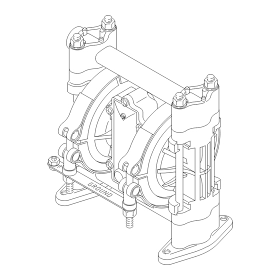
herkules 338 Air–Operated
Diaphragm Pump
100 psi (0.7 MPa, 7 bar) Maximum Fluid Working Pressure
100 psi (0.7 MPa, 7 bar) Maximum Air Input Pressure
Model No. 234019 Acetal Pump, Series E
US and Foreign Patents Pending
herkules Equipment Corporation
2760 Ridgeway Court
Walled Lake MI 48390
Read warnings and instructions.
309668A
01428B
Advertisement
Table of Contents

Subscribe to Our Youtube Channel
Related Manuals for Graco 234019


Summary of Contents for Graco 234019
- Page 1 Diaphragm Pump 309668A 100 psi (0.7 MPa, 7 bar) Maximum Fluid Working Pressure 100 psi (0.7 MPa, 7 bar) Maximum Air Input Pressure Model No. 234019 Acetal Pump, Series E US and Foreign Patents Pending Read warnings and instructions. 01428B...
-
Page 2: Table Of Contents
Table of Contents Symbols Safety Warnings ....... Installation ........Operation . - Page 3 WARNING WARNING TOXIC FLUID HAZARD Hazardous fluid or toxic fumes can cause serious injury or death if splashed in the eyes or on the skin, inhaled, or swallowed. D Know the specific hazards of the fluid you are using. D Store hazardous fluid in an approved container. Dispose of hazardous fluid according to all local, state and national guidelines.
-
Page 4: Installation
Installation General Information CAUTION D Contact your herkules distributor for assistance in Safe Operating Temperature planning a system to suit your needs. Minimum: 40_F (4.4_C); Maximum: 150_F (66_C). Operating outside these temperature limits will D Always use Genuine herkules Parts and Accesso- adversely affect the strength of the pump housing. - Page 5 Installation Grounding Ground all of this equipment: D Pump: Attach a ground wire (Y) to the grounding WARNING strip (112) with the screw (28), lockwasher (29) and nut (27), as shown in Fig. 1. Connect the clamp end FIRE AND EXPLOSION HAZARD of the ground wire to a true earth ground.
- Page 6 Installation Air Line Fluid Suction Line WARNING D The pump fluid inlet is 3/8 npt(f). See Fig. 2. Screw the fluid fitting into the pump inlet snugly. A bleed-type master air valve (B) is required in Use a compatible liquid thread sealant or PTFE your system to relieve air trapped between this tape on connections to prevent air from getting into...
- Page 7 Installation Fluid Pressure Relief Valve 3/8 npt(f) fluid inlet port 3/8 npt(f) fluid outlet port CAUTION Pressure relief valve Part No. 110134 (aluminum) Part No. 112119 (stainless steel) Some systems may require installation of a pres- Install valve between fluid inlet and outlet ports. sure relief valve at the pump outlet to prevent overpressurization and rupture of the pump or Connect fluid inlet line here.
- Page 8 Installation Air Exhaust Ventilation To exhaust to a remote location: 1. Remove the muffler (11) from the pump air exhaust port. WARNING WARNING FIRE AND EXPLOSION HAZARD Be sure to read FIRE OR EXPLOSION HAZARD and TOXIC FLUID HAZARD PRESSURIZED EQUIPMENT HAZARD on page 3, before operating this pump.
-
Page 9: Operation
Operation Pressure Relief Procedure 1. Be sure the pump is properly grounded. Read FIRE OR EXPLOSION HAZARD on page 3. WARNING 2. Check all fittings to be sure they are tight. Be sure PRESSURIZED EQUIPMENT HAZARD PTFE to use a compatible liquid thread sealant or The system pressure must be manually relieved to tape on all male threads. -
Page 10: Troubleshooting
Troubleshooting 1. Relieve the pressure before checking or servicing WARNING the equipment. To reduce the risk of serious injury whenever you are instructed to relieve pressure, always follow the 2. Check all possible problems and causes before Pressure Relief Procedure on page 9. disassembling the pump. - Page 11 Troubleshooting PROBLEM CAUSE SOLUTION There are air bubbles in the fluid. The suction line is loose, or there is Tighten the suction line. Use a a lack of thread sealant. compatible liquid thread sealant or PTFE R tape on connections. The diaphragm (401) is ruptured.
-
Page 12: Maintenance
Maintenance Lubrication Tightening the Clamps The air valve is designed to operate unlubricated, however if lubrication is desired, every 500 hours of When tightening the clamps (111), apply thread lubri- operation (or monthly) remove the hose from the pump cant to the bolts and be sure to torque the nuts (113) air inlet and add two drops of machine oil to the air to 50 to 60 in-lb (5.6 to 6.8 N-m). -
Page 13: Replacing The Air Valve
Service Replacing the Air Valve 3. Refer to the Valve Plate Detail in Fig. 5. Remove the two screws (10) holding the valve plate (13) to Tools Required the pump. Use an o-ring pick to remove the valve plate, seal (12), and bearing (9). D Torque wrench D Phillips screwdriver 4. - Page 14 Service VALVE PLATE DETAIL 01458 GREASE APPLICATION 01436B Torque oppositely and evenly to 8 to 14 in-lb (0.9 to 1.6 N-m). Torque to 5 to 7 in-lb (0.6 to 0.8 N-m). Apply grease (26{). 03412A Fig. 5 309668...
-
Page 15: Repairing The Air Valve
Service Repairing the Air Valve 2. Remove the air valve from the pump (see page 13). Tools Required 3. Remove the screw (15) and shift saddle (14). See D Torque wrench Fig. 6. D Phillips screwdriver 4. Disassemble the link assembly, consisting of the D O-ring pick actuator link (16), spacer (17), detent link (22), D Rubber mallet... - Page 16 Service Reassembly 1. If the detent collar (7) was removed, carefully 6. Squeeze the spring (3) and install it and the stop install a new collar in a new cover (2), using a (4) in the link assembly. The spring tension will rubber mallet.
- Page 17 Service 8. Grease the inside surfaces of the shift saddle (14) 9. Reinstall the air valve as explained on page 13. and install it as shown in Fig. 9. Hold the link assembly firmly in place and install the screw (15). Torque to 7 to 9 in-lb (0.8 to 1.0 N-m).
-
Page 18: Ball Check Valves
Service Ball Check Valves Tools Required 5. Remove the outer o-ring (108), seat (201), ball (301), ball guide (202), and inner o-ring (108) from D Torque wrench each of the covers (101). D 1/2” (13 mm) socket wrench D O-ring pick 6. - Page 19 Service 108* 202* 301* 201* 108* 108* 202* 301* 201* 108* Apply thread lubricant. Flat side faces ball. Beveled end up. Torque to 50 to 60 in-lb (5.6 to 6.8 N-m). Do not over-torque. Long threads at top. 02457C Fig. 10 309668...
-
Page 20: Diaphragm Repair
Service Diaphragm Repair Tools Required 4. Using a 7/16” socket wrench, remove the clamp nuts (113) and the grounding strip (112). Loosen D Torque wrench the clamps (111) and slip them over the housing D One 7/16” (11 mm) and two 1/2” (13 mm) (1). - Page 21 Service Reassembly 1. Install the shaft seals (30}) in the housing (1). 4. When installing the covers (101), slip the clamps Using a rubber mallet, carefully drive the bearings (111) over the housing (1) before positioning the (31}) flush into the housing so the holes face out. covers.
- Page 22 Service Grease shaft. Apply thread lubricant. Flat side faces ball. Beveled end up. Round side must face toward diaphragm. Apply medium-strength (blue) LoctiteR or equivalent. Torque to 75 to 85 in-lb (8.5 to 9.6 N-m) at 100 rpm maximum using a 1/2-in.
-
Page 23: Parts
Parts Air Motor Parts List (Matrix Column 2) Ref. Ref. Digit Part No. Description Digit Part No. Description 187705 HOUSING, center; 187724 LINK, actuator; sst polypropylene; 188175 SPACER, link; acetal see page 24 111750 WASHER, plain; sst 187706 COVER, air valve; polypropylene 111624 O-RING;... - Page 24 Parts 108* 202* 401* 301* 201* 108* *404 108* 202* 301* 201* 108* * Included in Pump Repair Kit, which may be purchased separately. { Included in Air Valve Kit 239952, which may be pur- chased separately. See parts list on page 23. Y Replacement Danger and Warning labels, tags and cards are available at no cost.
- Page 25 Parts Fluid Section Parts List (Matrix Column 3) Ref. Ref. Digit Part No. Description Digit Part No. Description 187701 COVER, fluid; acetal with 187701 COVER, fluid; acetal with conductive sst fibers conductive sst fibers 235337 MANIFOLD; acetal with 239146 MANIFOLD; acetal with conductive sst fibers conductive sst fibers;...
-
Page 26: Technical Data And Performance Charts
Technical Data PTFE Pumps with r Diaphragms Maximum fluid working pressure . . . 100 psi (0.7 MPa, 7 bar) Fluid inlet and outlet size..... . . 3/8 npt(f) Air pressure operating range . -
Page 27: Dimensions
Dimensions FRONT VIEW SIDE VIEW 2.53 in. (64.5 mm) 1/4 npt(f) Air Inlet 3/8 npt(f) Fluid Outlet 6.18 in. 8.13 in. (157 mm) (206.5 mm) 7.24 in. (184 mm) 6.05 in. (153.5 mm) 1.06 in. (27 mm) 1.13 in. 3/8 npt(f) 3/8 npt(f) (28.5 mm) 5.3 in. -
Page 28: Herkules Information
herkules Information TO PLACE AN ORDER, contact your herkules distributor, or call the following number to identify the distributor closest to you: 1–800–444–4351 Toll Free All written and visual data contained in this document reflects the latest product information available at the time of publication. herkules reserves the right to make changes at any time without notice.
Need help?
Do you have a question about the 234019 and is the answer not in the manual?
Questions and answers