Graco Check-Mate 800 Instructions Manual
Hide thumbs
Also See for Check-Mate 800:
- Instructions-parts list manual (42 pages) ,
- Instructions for use manual (22 pages) ,
- Instructions manual (22 pages)
Table of Contents
Advertisement
Quick Links
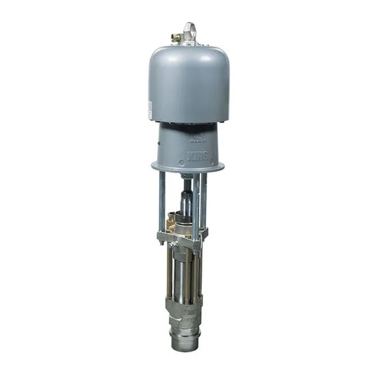
Instructions
Check-Mate
Stainless Steel
Stainless Steel pumps with Priming Piston and Severe-Duty® Rod Cylinder for transferring
common industrial coatings and adhesives. For professional use only.
Model 236462, Series B, 65:1 Ratio
®
with King
Air Motor and 236612 Displacement Pump
5850 psi (40 MPa, 403 bar) Maximum Working Pressure
90 psi (0.6 MPa, 6.2 bar) Maximum Air Input Pressure
Model 241519, Series B, 65:1 Ratio
®
with Quiet King
Air Motor and 236612 Displacement Pump
5850 psi (40 MPa, 403 bar) Maximum Working Pressure
90 psi (0.6 MPa, 6.2 bar) Maximum Air Input Pressure
Model 234978, Series A, 31:1 Ratio
®
with Bulldog
Air Motor and 236612 Displacement Pump
3100 psi (21 MPa, 214 bar) Maximum Working Pressure
100 psi (0.7 MPa, 7 bar) Maximum Air Input Pressure
See page 28 for technical specifications.
Important Safety Instructions
Read all warnings and instructions in this
manual before using the equipment.
Save these instructions.
®
800 Pumps
308352E
EN
TI03820
Advertisement
Table of Contents

Related Manuals for Graco Check-Mate 800


Summary of Contents for Graco Check-Mate 800
- Page 1 Instructions ® Check-Mate 800 Pumps 308352E Stainless Steel Stainless Steel pumps with Priming Piston and Severe-Duty® Rod Cylinder for transferring common industrial coatings and adhesives. For professional use only. Model 236462, Series B, 65:1 Ratio ® with King Air Motor and 236612 Displacement Pump 5850 psi (40 MPa, 403 bar) Maximum Working Pressure 90 psi (0.6 MPa, 6.2 bar) Maximum Air Input Pressure Model 241519, Series B, 65:1 Ratio...
-
Page 2: Table Of Contents
Required Tools......13 Graco Standard Warranty ....30 Disconnect the Displacement Pump . -
Page 3: Warnings
Warnings Warnings The following warnings are for the setup, use, grounding, maintenance, and repair of this equipment. The exclamation point symbol alerts you to a general warning and the hazard symbols refer to procedure-specific risks. When these symbols appear in the body of this manual or on warning labels, refer back to these Warnings. Product-specific hazard symbols and warnings not covered in this section may appear throughout the body of this manual where applicable. - Page 4 Warnings WARNING EQUIPMENT MISUSE HAZARD Misuse can cause death or serious injury. • Do not operate the unit when fatigued or under the influence of drugs or alcohol. • Do not exceed the maximum working pressure or temperature rating of the lowest rated system component.
-
Page 5: Installation
Installation Installation Grounding To maintain grounding continuity when flushing or relieving pressure: hold metal part of the dispense valve firmly to the side of a grounded metal pail, then trigger the dispense valve. Accessories The equipment must be grounded to reduce the risk of static sparking. -
Page 6: Flush Before Using Equipment
Installation Mounting • Air Regulator (F): controls pump speed and outlet pressure by adjusting the air pressure to the pump. Mount the pump (A) to suit the type of installation Locate the regulator close to the pump, but planned. F . -
Page 7: Typical Installation
. 2 is only a guide for selecting and installing system components and accessories. Contact your Graco distributor for Accessories are available from Graco. If you supply assistance in designing a system to suit your particular your own accessories, be sure they are adequately needs. -
Page 8: Operation
Operation Operation Pressure Relief Procedure Packing Nut/Wet Cup Before starting, fill the packing nut (2) 1/3 full with Graco Follow the Pressure Relief Procedure whenever Throat Seal Liquid (TSL) or compatible solvent. you see this symbol. The packing nut is torqued at the factory and is ready for operation. -
Page 9: Flush The Equipment
Operation Flush the Equipment Start and Adjust the Pump Keep hands and fingers away from the priming piston (21) during operation and whenever the pump is charged with air. The priming piston extends beyond the intake housing (19) to pull material into the pump To avoid fire and explosion, always ground equipment and can amputate a hand or finger caught between it and waste container. -
Page 10: Shutdown And Care Of The Pump
Operation To reduce the risk of fluid injection, do not use your To reduce the risk of overpressurizing your system, hand or fingers to cover the bleed hole on the which could cause component rupture and serious underside of the bleeder valve body (29) when injury, never exceed the Maximum Incoming Air priming the pump. -
Page 11: Troubleshooting
Troubleshooting Troubleshooting 1. Follow Pressure Relief Procedure, page 8, before checking or repairing the pump. 2. Check all possible problems and causes before disassembling pump. Problem Cause Solution Pump fails to operate The air supply is inadequate or air Increase the air supply; clear the air lines are restricted. - Page 12 1. Follow the Pressure Relief Procedure, page 8. NOTE: If you experience air motor icing, call your Graco 2. Disconnect the fluid hose and place a container at distributor.
-
Page 13: Repair
Repair Repair Required Tools Disconnect the Displacement Pump • Torque wrench • Bench vise, with soft jaws • Rubber mallet Be sure to use at least two people when lifting, • Hammer moving, or disconnecting the pump. This pump is too heavy for one person. -
Page 14: Connect The Displacement Pump
Repair Connect the Displacement 10. Torque the packing nut (2) to 136–149 N•m (100– 110 ft-lb). Pump Be sure to use at least two people when lifting, moving, or connecting the pump. This pump is too heavy for one person. If you are connecting the displacement pump to a motor which is still mounted (for example, on a ram), be sure to support the displacement pump while it is being connected, to... -
Page 15: Disassemble The Displacement Pump
Repair Disassemble the Displacement NOTE: The pump may separate at joints A, B, or C. See . 6. Pump NOTE: These instructions are written with the pump When disassembling the pump, lay out removed parts in separating at joint A. If it separates at joints B or C, sequence to ease reassembly. - Page 16 Repair NOTE: If the seat (37) is difficult to remove, insert a hammer and brass rod through the top of the housing (17) and drive the seat out. 8. Use a rubber mallet to drive the displacement rod (1) and the priming piston rod (18) out of the outlet housing (9) and cylinder (10).
- Page 17 Repair 13. If the priming piston rod (18) or piston (12) are 18. Unscrew the bleeder valve plug (20) completely damaged: Place the piston flats in a vise. Unscrew from the valve body (29). Clean the valve threads the priming piston rod (18). and the bleed hole.
-
Page 18: Assemble The Displacement Pump
Repair Assemble the Displacement 9. Torque the displacement rod (1) to 339–359 N•m (250–265 ft-lb). Pump 1. Lubricate the intake packings and install them in the valve body (16), with the lips of the v-packings facing up, in the following order (see F . - Page 19 Repair 13. Lubricate and install the throat packings and glands 17. Screw the housing onto the cylinder. See F . 13, in the packing housing (3) one at a time, with the page 20. lips of the v-packings facing down, in the following 18.
- Page 20 Repair Piston check valve (see Fig. 10). Intake check valve (see Fig. 11). Lubricate. Lips of v-packings must face down. Screw valve plug (20) completely into valve body (29). Torque to 136–149 N•m (100–110 ft-lb). Torque to 203–237 N•m (150–175 ft-lb). Torque to 522–542 N•m (385–400 ft-lb).
- Page 21 Repair 24. Screw the intake cylinder (19) into the intake 26. Check that the flats of the priming piston rod (18) housing (17). Use a pipe wrench to tighten the hex are accessible below the intake cylinder (19). If not, of the intake cylinder (19).
-
Page 22: Parts
Parts Parts Model 236462 Pump, Series B, 65:1 Ratio, with King Air Motor (shown) Model 241519 Pump, Series B, 65:1 Ratio, with Quiet King Air Motor Model 234978 Pump, Series A, 31:1 Ratio, with Bulldog Air Motor Ref. Part Description Qty. -
Page 23: Part 236612, Series A, Displacement Pump
Parts Part 236612, Series A, Displacement Pump 03818 308352E... - Page 24 Parts Model 236612, Series A, Displacement Pump Parts List Ref. Part Description Qty. Ref. Part Description Qty. 189516 CYLINDER, intake; stainless steel 189317 ROD, displacement; stainless 190293 PLUG, bleeder valve; stainless steel steel 236582 PACKING NUT/WET-CUP; 276378 PISTON, priming; stainless steel stainless steel 190241 SEAT, priming piston;...
-
Page 25: Performance Charts
Performance Charts Performance Charts To find Fluid Outlet Pressure (psi/MPa/bar) at a To find Pump Air Consumption (m3/min or scfm) at a specific fluid flow (lpm/gpm) and operating air pressure specific fluid flow (lpm/gpm) and air pressure (psi/MPa/bar): (psi/MPa/bar): 1. Locate desired flow along bottom of chart. 1. -
Page 26: Model 234978
Performance Charts Model 234978 A: 0.6 MPa, 6.2 bar (90 psi) air pressure B: 0.5 MPa, 4.9 bar (70 psi) air pressure C: 0.3 MPa, 2.8 bar (40 psi) air pressure Test Fluid: Number 10 Weight Oil Air Consumption Fluid Outlet Pressure cycles per minute cycles per minute scfm... -
Page 27: Dimensions
Dimensions Dimensions 94.28 mm (3.712 in.) 101.6 mm 94.28 mm (4.0 in.) (3.712 in.) 50.8 mm (2.0 in.) Three M16 x 2.0 Holes 11.1 mm 88 mm (0.437 in.) (3.464 in.) DIA (4) 0653 TI03820 Pump Model 236462 1376.7 mm 583.0 mm 793.7 mm 728.5 mm... -
Page 28: Technical Specifications
Technical Specifications Technical Specifications Models 236462 and 241519 Check-Mate 800 Pumps Metric Ratio 65:1 Maximum fluid working pressure 5850 psi 40 MPa, 403 bar Maximum air input pressure 90 psi 0.6 MPa, 6.2 bar Pump cycles per 3.8 liters (1 gal) -
Page 29: Model 234978
Technical Specifications Model 234978 Check-Mate 800 Pumps Metric Ratio 31:1 Maximum fluid working pressure 3100 psi 21 MPa, 214 bar Maximum air input pressure 100 psi 0.7 MPa, 7 bar Pump cycles per 3.8 liters (1 gal) 21 cycles Fluid flow at 60 cycles/min 2.8 gpm... -
Page 30: Graco Standard Warranty
With the exception of any special, extended, or limited warranty published by Graco, Graco will, for a period of twelve months from the date of sale, repair or replace any part of the equipment determined by Graco to be defective.
Need help?
Do you have a question about the Check-Mate 800 and is the answer not in the manual?
Questions and answers