Graco A Series Instructions Manual
Displacement pump
Hide thumbs
Also See for A Series:
- Instructions - parts manual (52 pages) ,
- Instructions-parts list manual (48 pages) ,
- Manual (36 pages)
Table of Contents
Advertisement
Quick Links
Instructions
Displacement
Pump
Use only genuine Graco Replacement Parts. Use of non-Graco replacement parts may void
warranty.
Models:
236787, Series A
235699, Series B
241320, Series A
Important Safety Instructions
Read all warnings and instructions in this manual.
Be familiar with the controls and the proper usage
of the equipment. Save these instructions.
Models 236787 and 235699 Shown
308190M
EN
Advertisement
Table of Contents

Related Manuals for Graco A Series


Summary of Contents for Graco A Series
- Page 1 Instructions Displacement Pump 308190M Use only genuine Graco Replacement Parts. Use of non-Graco replacement parts may void warranty. Models: 236787, Series A 235699, Series B 241320, Series A Important Safety Instructions Read all warnings and instructions in this manual. Be familiar with the controls and the proper usage of the equipment.
-
Page 2: Fire And Explosion Hazard
Check hoses and parts for signs of damage. Replace any damaged hoses or parts. • This system is capable of producing 3000 psi (210 bar/21 MPa). Use Graco replacement parts or accessories that are rated a minimum of 3000 psi (210 bar/21 MPa). -
Page 3: Personal Protective Equipment
Warnings WARNING EQUIPMENT MISUSE HAZARD Misuse can cause death or serious injury. • Do not operate the unit when fatigued or under the influence of drugs or alcohol. • Do not exceed the maximum working pressure or temperature rating of the lowest rated system component. -
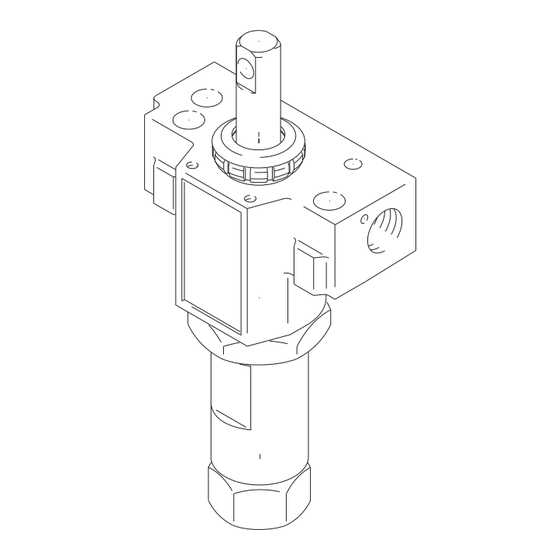
Page 4: Displacement Pump
Displacement Pump Displacement Pump Pressure Relief Procedure Intake Valve Repair Follow the Pressure Relief Procedure whenever 1. Unscrew the intake valve (118). Remove the o-ring you see this symbol. (119*), ball guide (120), stop pin (122*) and ball (121*) from the valve. 2. -
Page 5: Installing Pump
4. Tighten the packing nut (102) just enough to stop up and push out the pin (G). leakage, but no tighter. Fill the packing nut/wet-cup 1/3 full with Graco TSL. Push the plug (123) into the 5. Loosen the screws (H) and remove the pump. wet-cup. -
Page 6: Reassembling The Pump
Displacement Pump Reassembling the Pump DO NOT ALLOW NUT (110) TO MOVE RELATIVE NOTE 1: Alternate plastic and leather packings. See Fig TO PISTON (108) WHEN TIGHTENING PISTON 3. The lips of the throat V-packings face down. The lips AGAINST ROD of the piston V-packings face up. - Page 7 Displacement Pump 10. Install the packing nut (102) and plug (124), but 11. Place a new o-ring (116*) firmly in the cylinder (115) leave loose for now. See Fig 7. groove. See Fig 7. 12. Coat the piston rod and packings with oil. Carefully slide the assembly INTO THE TOP OF THE CYLIN- DER (115).
- Page 8 Parts Parts Model 236787, Series A: Includes 101 to 124 Model 235699, Series B: Includes 101 to 126 Model 241320, Series A: Includes 101 to 126 Part No. Description Part No. Description 114* 180073 GLAND, female, piston PUMP MANIFOLD CYLINDER, pump 187611 Models 236787 and 235699 236786...
- Page 9 Parts 103* 109* *105 104* 111* 106* *113 112* 114* Models *125 235699 241320 only *126 *116 *122 121* 119* 03148b 308190M...
-
Page 10: Technical Data
For patent information, see www.graco.com/patents. TO PLACE AN ORDER, contact your Graco distributor or call 1-800-690-2894 to identify the nearest distributor. All written and visual data contained in this document reflects the latest product information available at the time of publication.
Need help?
Do you have a question about the A Series and is the answer not in the manual?
Questions and answers