Graco Husky 715 Instructions-Parts List Manual
Air-operated diaphragm pumps
Hide thumbs
Also See for Husky 715:
- Instructions and parts list (37 pages) ,
- Instructions-parts list manual (36 pages) ,
- Instructions manual (36 pages)
Advertisement
Quick Links
INSTRUCTIONS–PARTS LIST
This manual contains important
warnings and information.
READ AND KEEP FOR REFERENCE.
INSTRUCTIONS
ALUMINUM
Husky
Diaphragm Pumps
50 psi (345 kPa, 3.4 bar) Maximum Fluid Working Pressure
50 psi (345 kPa, 3.4 bar) Maximum Air Input Pressure
Model No. 237311, Series D
Buna-N diaphragms and balls
Model No. 238226, Series D
Buna-N diaphragms and balls
Restricted air inlet to maximize pumping efficiency for
evacuation systems
Model No. 232106, Series D
Buna-N diaphragms and balls
Same as Model No. 238226, except air inlet and fluid
inlet and outlet ports face in the same direction to
facilitate wall mounting
LISTED
GRACO INC. P.O. BOX 1441
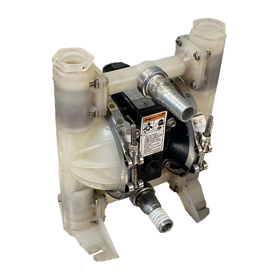
715 Air-Operated
Model No. 237311 and 238226 shown
COPYRIGHT 1995, GRACO INC.
Graco Inc. is registered to I.S. EN ISO 9001
First choice when
quality counts.
MINNEAPOLIS, MN 55440–1441
308573
Rev. S
04050
Advertisement

Subscribe to Our Youtube Channel
Related Manuals for Graco Husky 715


Summary of Contents for Graco Husky 715
- Page 1 LISTED Model No. 237311 and 238226 shown 04050 GRACO INC. P.O. BOX 1441 MINNEAPOLIS, MN 55440–1441 COPYRIGHT 1995, GRACO INC. Graco Inc. is registered to I.S. EN ISO 9001...
- Page 2 Read all instruction manuals, tags, and labels before operating the equipment. Use the equipment only for its intended purpose. If you are not sure, call your Graco distributor . Do not alter or modify this equipment. Use only genuine Graco parts and accessories.
- Page 3 WARNING TOXIC FLUID HAZARD Hazardous fluid or toxic fumes can cause serious injury or death if splashed in the eyes or on the skin, inhaled, or swallowed. Know the specific hazards of the fluid you are using. Store hazardous fluid in an approved container. Dispose of hazardous fluid according to all local, state and national guidelines.
- Page 4 Installation Grounding Air and fluid hoses : use only electrically conductive WARNING hoses. FIRE AND EXPLOSION HAZARD Air compressor : follow the manufacturer’s This pump must be grounded. Before recommendations. operating the pump, ground the system as explained below. Also read the sec- Suction device nozzle: must be bonded to metal tion FIRE OR EXPLOSION HAZARD on container from which it is suctioning by firm...
- Page 5 Code (NFPA 30A) and must comply with all local, well as the stress caused during operation. state and federal codes. The Husky 715 Pump can be used in a variety of Use a compatible, liquid thread sealant on all male installations. See Figs. 2 and 3 for examples.
- Page 6 Bay 1 Bay 2 Bay 3 Control valve Suction wand Suction hose G Fluid quick coupler Husky 715 pump Electrically conductive, bonded air supply line Electrically conductive, bonded fluid line to pump Electrically conductive, bonded waste oil line to storage tank Ground wire (required;...
- Page 7 Installation Air Line Fluid Supply Line Use electrically conductive fluid hoses (J or F). Be WARNING sure the lines are bonded all the way from the fluid supply to the grounded pump. An air line quick coupler (B) is required in your system to relieve air trapped between this valve The pump fluid inlet is 3/4 npt(f).
- Page 8 Torque to 3 to 6 ft-lb (4 to 8 N.m). Pressure Relief Kit 238428 is available for use on 1/4 npt(f) Air Inlet aluminum Husky 715 pumps and may be purchased 3/4 npt(f) Fluid Inlet separately. 3/4 npt(f) Fluid Outlet...
- Page 9 Installation Air Exhaust Ventilation The air exhaust port is 3/8 npt(f). Do not restrict the air exhaust port. Excessive exhaust restriction can cause erratic pump operation. WARNING To exhaust to a remote location: FIRE AND EXPLOSION HAZARD Be sure to read FIRE OR EXPLOSION 1.
- Page 10 Operation Pressure Relief Procedure Starting and Adjusting the Pump All Systems WARNING WARNING PRESSURIZED EQUIPMENT HAZARD The equipment stays pressurized until pressure is TOXIC FLUID HAZARD manually relieved. To reduce the risk of serious injury from pressurized fluid, accidental spray from Hazardous fluid or toxic fumes can cause serious injury or death if splashed the gun or splashing fluid, follow this procedure...
- Page 11 Operation Waste Receiver Evacuation Systems, or General 5. Place the suction wand (E) in the differential or Fluid Transfer Applications (See Fig. 3) fluid to be pumped. 1. Connect the suction hose (F) to the waste oil 6. Pull the control valve (D) handle down to start the receiver (M) with a fluid quick coupler (G).
- Page 12 Maintenance Lubrication Tightening the Clamps The air valve is designed to operate unlubricated, When tightening the clamps (109), apply thread however if lubrication is desired, every 500 hours of lubricant to the bolts and be sure to torque the nuts operation (or monthly) remove the hose from the pump (110) to 50 to 60 in-lb (5.6 to 6.8 N.m).
- Page 13 Notes...
- Page 14 Troubleshooting 1. Relieve the pressure. WARNING 2. Check all possible problems and causes before To reduce the risk of serious injury whenever you disassembling the pump. are instructed to relieve pressure, always follow the Pressure Relief Procedure on page 10. PROBLEM CAUSE SOLUTION...
- Page 15 Troubleshooting PROBLEM CAUSE SOLUTION Air bubbles in fluid. Suction line is loose. Tighten. Diaphragm (401 ) ruptured. Replace. See page 23. Loose manifolds (102) or damaged Tighten manifold screws (105); o-rings (113*). replace o-rings (113*). See page 22. Loose fluid side diaphragm plates Tighten screw (114***).
- Page 16 Service Tools Required WARNING Torque wrench To reduce the risk of serious injury whenever you Set of socket wrenches are instructed to relieve pressure, always follow the 1/8” EZY-OUT bearing extractor Pressure Relief Procedure on page 10. O-ring pick 1. Relieve the pressure. Replacing the Air Valve 2.
- Page 17 Service 3. Refer to Fig. 9. Use an o-ring pick to remove the bearings (9 and 24). 4. Remove the two screws (23) holding the valve plate (13) to the pump. Use an o-ring pick to remove the valve plate and seal (12). Clean and inspect the parts.
- Page 18 Service 16. Install the six screws (10) and torque oppositely CAUTION and evenly to 20 to 25 in-lb (2.3 to 2.8 N.m). See Fig. 8. If you are replacing the diaphragms, you must rein- stall the air valve before installing the diaphragms, as the diaphragms will force the pilot pins into the air valve area.
- Page 19 Service Tools Required 2. Remove the air valve (A) from the pump. See page 16. Torque wrench 3. Remove the screw (15 ) and shift saddle (14 ). Phillips screwdriver See Fig. 12. O-ring pick Rubber mallet 4. Disassemble the link assembly, consisting of the actuator link (16 ), spacer (17 ), detent link (22 ), Repairing the Air Valve spring (3 ), stop (4 ), and valve cup (5 ).
- Page 20 Service Reassembly 1. If the detent collar (7 ) was removed, install a new 6. Squeeze the spring (3 ) and install it and the stop collar in a new cover (2 ). Using a rubber mallet, (4 ) in the link assembly. The spring tension will carefully press fit the detent collar (7 ) into the hold all these parts together.
- Page 21 Service 8. Grease the inside surfaces of the shift saddle (14 ) and install it as shown in Fig. 15. Hold the link assembly firmly in place and install the screw Apply grease (25 ). (15 ). Torque to 7 to 9 in-lb (0.8 to 1.0 N.m). Install the o-ring (19 ) on the cover (2 ).
- Page 22 Service Tools Required Torque wrench 9/16” socket wrench O-ring pick Ball Check Valves NOTE: Ball Check Repair Kit D05270 is available. Kit 113* parts are marked with an asterisk, for example (301*). Use all the parts in the kit for the best results. Always 202* Torque to 3 to 6 ft-lb replace the o-rings (113*) with new ones whenever...
- Page 23 Service Tools Required 5. Pull the other diaphragm and the shaft out of the pump housing (1). Clamp the shaft in a vise with Torque wrench soft jaws (or grip the flats with a wrench) and disassemble the remaining diaphragm assembly. Set of socket wrenches Phillips screwdriver NOTE: In Step 6, use a 13/32 in.
- Page 24 Service Reassembly 4. Install the clamps (109) in the reverse order of step 3 on page 23. The clamp bolts should be on CAUTION the air valve side of the housing, and pointing down toward the bottom of the pump. If you have removed the air valve (A), you must reinstall it before reinstalling the diaphragms.
- Page 25 Service 116*** 118*** 114*** 115 *** Detail of Grounding Strip and Clamps Grease. Apply medium-strength (blue) Loctite or equivalent to threads, and torque to 65 to 85 in-lb (8.5 to 9 N.m) at 100 rpm maximum. Do not over-torque. Curved side of plates (1 16***) and (118***) must face diaphragms (401).
- Page 26 Notes...
- Page 27 Parts Air Motor Parts List Ref. Ref. Part No. Description Part No. Description 189531 HOUSING, center; aluminum; 188175 SPACER, link; acetal see page 29 111750 WASHER, plain; sst 187706 COVER, air valve; polypropylene 111624 O-RING; buna-N 187722 SPRING; sst 111625 O-RING;...
- Page 28 Parts Fluid Section Parts List Ref. Ref. Part No. Description Part No. Description 185622 COVER, fluid; aluminum 100790 SCREW; 10–24; 0.31 in. (8 mm) long 185624 MANIFOLD; aluminum 100718 LOCKWASHER, 189220 LABEL, warning internal tooth; no. 10 112912 SCREW; 3/8–16; 100179 NUT, hex;...
- Page 29 Parts Part of Air Valve Kit 239952. See page 27. Part of Diaphragm Shaft Kit. See page 27. *113 *202 *301 125** *201 *113 116*** 118*** 115 *** 114*** *113 *202 *301 Detail of Grounding Strip *201 *113 109 (Ref) 04059...
- Page 30 6.97 in. fluid inlet (177.0 mm) 8.69 in. (220.7 mm) 04055 04056 Mounting Hole Layouts WALL BRACKET 221167 HUSKY 715 PUMP (BOTTOM VIEW) (viewed from wall) 9.0 in. 6.62 in. (228.6 mm) (168.1 mm) 4.29 in. (109.2 mm) 8 in.
- Page 31 Performance Charts PUMPING RATE DECREASE AT DIFFERENT SUCTION LIFTS EXAMPLE: At a suction lift of 10 ft (3.05 m), the pump flow rate is decreased by 20 percent. (1.52) (3.05) (4.57) (6.1) (7.62) SUCTION LIFT IN FEET (METERS)
- Page 32 Performance Charts U.L. Listed Aluminum Husky 715 Fluid Outlet Pressure, Model 237311 Test Conditions: Pump tested in water with inlet submerged. (345 kPa, 3.4 bar) Fluid Pressure Curves A at 50 psi (345 kPa, 3.4 bar) air pressure B at 35 psi (241 kPa, 2.4 bar) air pressure (276 kPa, 2.8 bar)
- Page 33 Performance Charts U.L. Listed Aluminum Husky 715 Air Consumption, Model 237311 Test Conditions: Pump tested in water with inlet submerged. Ë Ë Ë Ë Ë Ë Ë Ë Ë Ë Ë Ë Ë Ë Ë Ë Ë Ë Ë Ë Ë Ë Ë Ë Ë Ë Ë...
- Page 34 Performance Charts U.L. Listed Aluminum Husky 715 Fluid Outlet Pressure, Models 238226 and 232106 (with restricted air inlet) Test Conditions: Pump tested in water with inlet submerged. (345 kPa, 3.4 bar) Fluid Pressure Curve at 40 psi (276 kPa, 2.8 bar) air pressure (276 kPa, 2.8 bar)
- Page 35 Performance Charts U.L. Listed Aluminum Husky 715 Air Consumption, Models 238226 and 232106 (with restricted air inlet) Test Conditions: Pump tested in water with inlet submerged. Ë Ë Ë Ë Ë (0.224) Ë Ë Ë Ë Ë Ë Ë Ë Ë Ë...
- Page 36 Graco’s written recommendations. This warranty does not cover, and Graco shall not be liable for general wear and tear , or any malfunction, damage or wear caused by faulty installation, misapplication, abrasion, corrosion, inadequate or improper maintenance, negligence, accident, tampering, or substitution of non-Graco component parts.
Need help?
Do you have a question about the Husky 715 and is the answer not in the manual?
Questions and answers