Banner Sure Cross DXM150-S Series Instruction Manual
Industrial wireless controller wireless modbus slave
Hide thumbs
Also See for Sure Cross DXM150-S Series:
- Instruction manual (43 pages) ,
- Product manual (37 pages)

Related Manuals for Banner Sure Cross DXM150-S Series


Summary of Contents for Banner Sure Cross DXM150-S Series
- Page 1 DXM150-Sx Wireless Modbus Slave Instruction Manual Original Instructions 195455 Rev. C 23 July 2020 © Banner Engineering Corp. All rights reserved 195455...
-
Page 2: Table Of Contents
8.2 FCC and ISED Certification, 900 MHz, 1 Watt Radios ........................26 8.3 FCC and ISED Certification, 2.4GHz ............................. 27 8.4 Contact Us .....................................29 8.5 Warnings ......................................29 8.6 Banner Engineering Corp. Limited Warranty ..........................29 8.7 Glossary of Wireless Terminology ..............................29... -
Page 3: System Overview
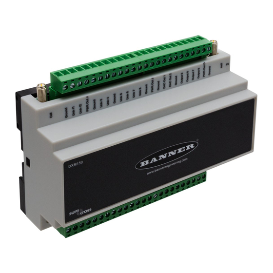
DXM150-Sx Wireless Modbus Slave 1 System Overview 1.1 DXM150-S1 System Overview Banner's DXM Logic Controller integrates Banner's wireless radio and local I/O for a remote I/O device. Inputs/Outputs—On-board universal and programmable I/O ports connect to local sensors, indicators, and control Connectivity equipment. - Page 4 DXM150-Sx Wireless Modbus Slave Important: • Electrostatic discharge (ESD) sensitive device • ESD can damage the device. Damage from inappropriate handling is not covered by warranty. • Use proper handling procedures to prevent ESD damage. Proper handling procedures include leaving devices in their anti-static packaging until ready for use; wearing anti-static wrist straps; and assembling units on a grounded, static-dissipative surface.
-
Page 5: Ism Radio
DXM150-Sx Wireless Modbus Slave 2 ISM Radio 2.1 ISM Radio Board (Slave ID 1) Plug the ISM radio into the I/O base board with the U.FL antenna connector closest to the SMA connectors. A - Antenna connector B - Button C - LED D1 - DIP switches D2 - DIP Switches... -
Page 6: Application Mode
DXM150-Sx Wireless Modbus Slave D1 Switches D2 Switches Device Settings Transmit power OFF* 900 MHz radios: 1.00 Watt (30 dBm) 2.4 GHz radios: 0.065 Watts (18 dBm) and 60 ms frame Transmit power 900 MHz radios: 0.25 Watts (24 dBm) 2.4 GHz radios: 0.065 Watts (18 dBm) and 40 ms frame Application mode: Modbus... -
Page 7: Binding The Ism Radio Of A Modbus Slave
DXM150-Sx Wireless Modbus Slave 2.3 Binding the ISM Radio of a Modbus Slave A DXM (for example, model DXM1x0-S*R2) contains two boards: a MultiHop ISM radio and an I/O base board. Each board is a separate Modbus device and requires a unique Modbus ID. •... -
Page 8: O Base Boards
DXM150-Sx Wireless Modbus Slave 3 I/O Base Boards 3.1 Board Connections for the S1 Models Figure 2. Board Connections Input 2B Analog Output 1 (0 to 10 V) 12 to 30 V DC or solar power in (+) Ground Ground Ground Output 1 Normally Open PWR Out - Jumper... -
Page 9: Board Connections For The S2 Models
DXM150-Sx Wireless Modbus Slave 3.2 Board Connections for the S2 Models Figure 3. Board Connections ********* THIS IS THE TABLE FOR THE DXM150-B2. PLEASE MARK THIS UP FOR THE DXM150-S2. ********* Input 2B Analog Output 1 (0–20 mA or 0–10 V) 12 to 30 V DC or solar power in (+) Ground Ground... -
Page 10: Dip Switches For The I/O Board
DXM150-Sx Wireless Modbus Slave Radio LED RS-485 Jumpers Modbus Slave ID DIP Switches Radio Module Antenna RS-232 Jumpers Rotary Dials SAM4 Processor Board Connection 3.3 DIP Switches for the I/O Board The DXM150-Sx Wireless Modbus Slave I/O board DIP switches are set from the factory to Modbus Slave ID 11. 3.4 I/O Board Jumpers Hardware jumpers on the DXM I/O board allow the user to select alternative pin operations. -
Page 11: Applying Power To The B2 Or S2 Models
DXM150-Sx Wireless Modbus Slave 3.6 Applying Power to the B2 or S2 Models Apply power using either 12 to 30 V DC or a 12 V DC solar panel and 12 V sealed lead acid battery. Description Pin 1 No connection Pin 2 12 to 30 V DC input (+) or solar panel connection (+) Pins 3, 5, 8, 13, 18, 24, 25,... -
Page 12: Inputs And Outputs
DXM150-Sx Wireless Modbus Slave Parameter Description Pin 9 RS-232 Tx Serial RS-232 connection. This bus must use a ground connection between devices to operate correctly. Pin 10 RS-232 Rx Pin 13 Secondary RS-485 – Not used Pin 14 Secondary RS-485 + Pin 15 CANL –... - Page 13 Thermistor Input A thermistor input must use a 10k thermistor between ground and the universal input. The thermistor must be a 10k NTC (Banner model number BWA-THERMISTOR-002) or equivalent. Select the temperature conversion of degrees I/O Base Board . C (default) or degrees F by writing to the Modbus registers defined in Example: Configure Input 1 as a Synchronous Counter 1.
-
Page 14: Pnp And Npn Outputs For The B1, B2, And S2 Models
DXM150-Sx Wireless Modbus Slave 2. Launch the DXM Configuration Software software. 3. Connect to the DXM by selecting the Device > Connection Settings menu option. You may connect using either USB or Ethernet. 4. Select a COMM port from the drop-down list and click Connect. 5. -
Page 15: Nmos Outputs For The S1 Models
DXM150-Sx Wireless Modbus Slave 3.10.4 NMOS Outputs for the S1 Models Output Description Wiring Pin 25 Output Pin 27 Less than 1 A maximum current at 30 V DC Pin 28 NMOS Discrete ON-State Saturation: Less than 0.7 V at 20 mA Outputs ON Condition: Less than 0.7 V OFF Condition: Open... -
Page 16: Additional Information
DXM150-Sx Wireless Modbus Slave 4 Additional Information 4.1 Setting the Modbus Slave ID on the I/O Base Board Only DXM150-Sx and SxR2 Modbus Slave models require that the Modbus Slave ID to be adjusted on the I/O base board. The DXM150-Sx Wireless Modbus Slave devices use DIP switch J and rotary dial K to set the Modbus slave ID. The device can use a Modbus register 6804 in the I/O board to access the full range of Modbus Slave IDs. -
Page 17: Modbus Register Summary
DXM150-Sx Wireless Modbus Slave 4.2 Modbus Register Summary 4.2.1 Modbus Registers The DXM150-S1 and S2 devices can have two Modbus IDs: one for the MultiHop ISM radio (by default, set to 1) and one for the I/O base (by default, set to 11). All Modbus registers are defined as 16-bit Modbus Holding Registers. -
Page 18: Modbus Configuration Registers For The Discrete And Universal Inputs
DXM150-Sx Wireless Modbus Slave Board Output Settings Register Description Values Register Description 3704 Enable Discrete Output 1 0 = NPN; 1 = PNP 3705 Invert Output 3724 Enable Discrete Output 2 0 = NPN; 1 = PNP 3725 Invert Output 3744 Enable Discrete Output 3 0 = NPN;... -
Page 19: Modbus Configuration Registers For The I/O (Definitions)
DXM150-Sx Wireless Modbus Slave Universal Input Register Ranges Register Types Unit Minimum Value Maximum Value Discrete input/output Universal input 0 to 10 V 10000 * Universal input 0 to 20 mA µA 20000 * Universal input temperature (–40 °C to +85 °C) C or F, signed, in tenths of a degree –400 Universal potentiometer... -
Page 20: Modbus Configuration Registers For Power
DXM150-Sx Wireless Modbus Slave 4.2.6 Modbus Configuration Registers for Power To monitor the input power characteristics of the DXM, read the following power Modbus registers. The on-board thermistor is not calibrated, but can be used as a non-precision temperature input. Modbus Register Description 6071... - Page 21 Solar Panel Banner solar panels come in two common sizes for the DXM: 5 Watt and 20 Watt. Both panels are designed to work with the DXM but provide different charging characteristics. Use the 5 watt panel for light duty operation and use the 20 watt panel when you require greater charging capabilities.
-
Page 22: Recommended Solar Configurations
DXM150-Sx Wireless Modbus Slave 4.3.3 Recommended Solar Configurations These solar panel and battery combinations assume direct sunlight for at least two to three hours a day. Solar insolation maps provide approximate sun energy for various locations. The depth of battery discharge is assumed to be 50 percent. Solar Panel and Battery Combinations for a DXM System Battery Capacity (Ahr) 3 Solar Panel... -
Page 23: Dxm150 Dimensions
DXM150-Sx Wireless Modbus Slave 5 DXM150 Dimensions All measurements are listed in millimeters [inches], unless noted otherwise. 59.5 mm [2.34”] 35 mm 156 mm [1.38”] [6.14”] 85 mm [3.35”] 94.6 mm [3.72”] www.bannerengineering.com - Tel: + 1 888 373 6767... -
Page 24: Troubleshooting
DXM150-Sx Wireless Modbus Slave 6 Troubleshooting 6.1 Restoring Factory Default Settings for the I/O Base Board To reset the I/O base board to factory defaults, write to two Modbus registers in the base board. The default slave ID for the base board is 11. -
Page 25: Accessories
DXM150-Sx Wireless Modbus Slave 7 Accessories For a complete list of all the accessories for the Sure Cross wireless product line, please download the Accessories List (p/n b_3147091). Cordsets Misc Accessories MQDC1-506—5-pin M12/Euro-style, straight, single ended, 6 ft BWA-CG.5-3X5.6-10—Cable Gland Pack: 1/2-inch NPT, Cordgrip for 3 holes of 2.8 to 5.6 mm diam, 10 pack MQDC1-530—5-pin M12/Euro-style, straight, single ended, 30 ft BWA-HW-052—... -
Page 26: Product Support And Maintenance
DXM150-Sx Wireless Modbus Slave 8 Product Support and Maintenance 8.1 DXM150 Documentation List • DXM Wireless Controller Sell Sheet, p/n 194063 • DXM150-B1 Wireless Controller Datasheet, p/n 178136 • DXM150-B2 Wireless Controller Datasheet, p/n 195952 • DXM150-Bx Wireless Controller Instruction Manual, p/n 190038 •... -
Page 27: Fcc And Ised Certification, 2.4Ghz
DXM150-Sx Wireless Modbus Slave 8.2 Note This equipment has been tested and found to comply with the limits for a Class A digital device, pursuant to Part 15 of the FCC Rules. These limits are designed to provide reasonable protection against harmful interference in a residential installation. - Page 28 DXM150-Sx Wireless Modbus Slave 8.3 FCC Notices IMPORTANT: The transmitter modules DX80-2400 and SX243 have been certified by the FCC / ISED for use with other products without any further certification (as per FCC section 2.1091). Changes or modifications not expressly approved by the manufacturer could void the user’s authority to operate the equipment.
-
Page 29: Contact Us
When using other antennas, verify you are not exceeding the transmit power levels allowed by local governing agencies. This device has been designed to operate with the antennas listed on Banner Engineering’s website and having a maximum gain of 9 dBm. Antennas not included in this list or having a gain greater that 9 dBm are strictly prohibited for use with this device. - Page 30 DXM150-Sx Wireless Modbus Slave baseline filter Under normal conditions, the ambient magnetic field fluctuates. When the magnetic field readings drift (M-GAGE) below a threshold setting, the baseline or drift filter uses an algorithm to slowly match the radio device’s baseline to the ambient magnetic field. binding (DX80 Binding Nodes to a Gateway ensures the Nodes only exchange data with the Gateway they are bound star networks)
- Page 31 DXM150-Sx Wireless Modbus Slave counter - The frequency counter calculates the frequency of the input signal, in Hz. frequency Frequency counters can be used to measure flow rates, such as measuring the flow rate of items on a conveyor or the speed at which a windmill spins. cyclic reporting Cyclic reporting is when the Gateway polls the Node at user-defined intervals.
- Page 32 DXM150-Sx Wireless Modbus Slave Gateway Link Failure—Gateway link failures are determined by three global parameters: Polling Interval, Maximum Missed Message Count and Re-link Count. When the Node’s Gateway Link Failure flag is set and the Gateway determines a timeout condition exists for a Node, any outputs linked from the failing Node are set to the user-defined default state.
- Page 33 Flex Power Flex Power ® Banner’s technology allows for a true wireless solution by allowing the device to operate using either 10 to 30 V DC, 3.6 V lithium D cell batteries, or solar power. This unique power management system can operate a Flex Power Node and an optimized sensing device for up to 5 years on a single lithium D cell.
- Page 34 DXM150-Sx Wireless Modbus Slave heartbeat mode In heartbeat mode, the Nodes send "heartbeat" messages to the Gateway at specific intervals to indicate the radio link is active. The heartbeat is always initiated by the Node and is used only to verify radio communications.
- Page 35 DXM150-Sx Wireless Modbus Slave line of sight Line of sight is the unobstructed path between radio antennas. link failures A Host Link Failure occurs when the defined timeout period, typically about four seconds, elapses with no communication between the host system (or Modbus master device) and the DX80 Gateway. A Gateway Link Failure refers to the radio link between a Node and the Gateway and is determined by three global parameters: Polling Interval, Maximum Missed Message Count, and Re-link Count.
- Page 36 DXM150-Sx Wireless Modbus Slave Node Nodes are remote I/O slave devices within Banner's wireless sensor networks. Sensors and other devices connect to the Node's inputs or outputs, allowing the Node to collect sensor data and wirelessly transmit it to the Gateway. Every Sure Cross device is a transceiver, meaning it can transmit and receive data.
- Page 37 DXM150-Sx Wireless Modbus Slave I/O Status Change of state reporting sets the system to report only when the value crosses the threshold setting. rotary dial See: address mode address mode Site Received Signal An RSSI is the measurement of the strength of received signals in a wireless environment. See Strength Survey .
- Page 38 Slave radios acknowledge receipt of messages transmitted from the master radio. For more information on Banner's star network products, refer to the Sure Cross Performance DX80 Wireless I/O Network Instruction Manual (p/n 132607)
- Page 39 DXM150-Sx Wireless Modbus Slave tau filter Set to zero (0) to turn off the tau filter. Set to 1 (weakest filter) through 6 (strongest filter) to turn on the tau filter. (In the DX80 products, the Low Pass Filter is a combination of the median filter and the tau filter.) TCP/IP TCP/IP stands for Transfer Control Protocol / Internet Protocol and describe several layers in the OSI...
- Page 40 DXM150-Sx Wireless Modbus Slave www.bannerengineering.com - Tel: + 1 888 373 6767...
Need help?
Do you have a question about the Sure Cross DXM150-S Series and is the answer not in the manual?
Questions and answers