
Related Manuals for Banner DXM150-Bx


Summary of Contents for Banner DXM150-Bx
- Page 1 DXM150-Bx and 1500-Bx Wireless Con- troller Instruction Manual Original Instructions p/n: 190038 Rev. L June 05, 2023 © Banner Engineering Corp. All rights reserved.
-
Page 2: Table Of Contents
Set a Static IP Address ..................................17 Configuration Instructions ..................................18 Configuring the Controller..................................18 Introduction to Traditional Setup Mode ..............................18 Banner Engineering Corp Limited Warranty .............................. 21 ............................................. 22 Chapter 3 ISM Radio Board (Slave ID 1) MultiHop Radio DIP Switches..................................23 Application Mode ....................................24 Baud Rate and Parity................................... - Page 3 Chapter 6 Cellular Modem Boards Cellular Modem Board....................................43 Cellular Power Requirements ..................................43 Using the DXM Cellular Modem ................................. 44 Activating a Cellular Modem..................................44 Install the Cellular Modem (DXM100, 150, 700, and 1000 Models) ....................45 Install the Cellular Modem (DXM1200 Models) ........................... 46 Activate a 4G LTE CAT M1 Cellular Plan ............................
- Page 4 FCC and ISED Approved Antennas................................102 FCC and ISED Certification, 2.4GHz................................ 103 FCC Notices ......................................103 FCC and ISED Approved Antennas................................103 Notas Adicionales ....................................104 Mexican Importer...................................... 104 ANATEL ........................................104 Contact Us ........................................ 104 Warnings........................................105 Banner Engineering Corp Limited Warranty .............................. 21 ........................................... 106...
-
Page 5: Chapter 1 System Overview
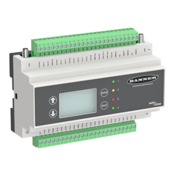
System Overview for the DXM150-B1 Banner's DXM Logic Controller integrates Banner's wireless radio, cellular connectivity, and local I/O to provide a platform for the Industrial Internet of Things (IIoT). Various combinations of I/O and connectivity are available based on the different mod- els. -
Page 6: System Overview For The Dxm150-B2
Four multicolored LEDs: green, amber, and red Viewing sensor information Programmable behavior System Overview for the DXM150-B2 Banner's DXM Logic Controller integrates Banner's wireless radio, cellular connectivity, and local I/O to provide a platform for the Industrial Internet of Things (IIoT). Inputs and Outputs Connectivity... -
Page 7: System Overview For The Dxm1500-B1
Four multicolored LEDs: green, amber, and red Viewing sensor information Programmable behavior System Overview for the DXM1500-B1 Banner's DXM Logic Controller integrates Banner's wireless radio, cellular connectivity, and local I/O to provide a platform for the Industrial Internet of Things (IIoT). Inputs and Outputs Connectivity... -
Page 8: System Overview For The Dxm1500-B2
Four multicolor LEDs: green, amber, and red Viewing sensor information Programmable behavior System Overview for the DXM1500-B2 Banner's DXM Logic Controller integrates Banner's wireless radio, cellular connectivity, and local I/O to provide a platform for the Industrial Internet of Things (IIoT). Inputs and Outputs Connectivity... - Page 9 DXM150-Bx And 1500-Bx Wireless Controller Instruction Manual Continued from page 8 Local Registers Type Description 7001–8000 32-bit non-volatile integer Data flash, non-volatile > 10000 Read-only virtual registers, system-level data Inputs and Outputs Connectivity On-board universal and programmable I/O ports connect to lo- The DXM's wired and wireless connectivity options make it cal sensors, indicators, and control equipment.
-
Page 10: Hardware Overview
DXM150-Bx And 1500-Bx Wireless Controller Instruction Manual Hardware Overview The DXM can have several different configurations. The DXM has a model number label on the housing. Use the model num- ber and model table to identify which boards are included in the your controller. - Page 11 DXM150-Bx And 1500-Bx Wireless Controller Instruction Manual Base Radio Configuration DXM1500- Blank = None B2 = Modbus controller for high I/O count applications Power: 12-30 V DC / Solar / Battery Comms: RS-485 and RS-232 w/flow control or secondary RS-485...
-
Page 12: Dxm Configuration Software
DXM150-Bx And 1500-Bx Wireless Controller Instruction Manual ISM Radio—The ISM radio, either a MultiHop or DX80 Gateway, fits on the I/O base board in the parallel sockets. Install the ISM radio so the U.FL antenna connection is to the side with the SMA antenna connectors. Connect the U.FL cable from the ISM radio U.FL to the right side U.FL connector. -
Page 13: Dxm Modbus Overview
Modbus port 502 is used by the DXM for all Modbus TCP/IP client Modbus RTU bus to communicate with locally connect- requests. ed Modbus devices or uses the Banner wireless radio to com- All internal registers are available to the host system concur- municate with remote Modbus devices. - Page 14 Blank page...
-
Page 15: Chapter 2 Quick Start Guide
DXM150-Bx And 1500-Bx Wireless Controller Instruction Manual Chapter Contents Device Setup ........................................15 Configuration Instructions ....................................18 Banner Engineering Corp Limited Warranty ..............................21 ............................................22 Chapter 2 Quick Start Guide Device Setup Apply Power to the Controller Follow these instructions to apply 12–30 V DC power to the controller using a wall plug. - Page 16 DXM150-Bx And 1500-Bx Wireless Controller Instruction Manual Separate radios by two meters when running the binding procedure. Put only one DXM Gateway into binding mode at a time to prevent binding to the wrong Gateway. Enter binding mode on the DXM radio: Use the arrow keys to select the ISM Radio menu on the LCD and press ENTER.
-
Page 17: Set A Static Ip Address
DXM150-Bx And 1500-Bx Wireless Controller Instruction Manual ◦ For board-level radios, triple-click the button. ◦ For radios without buttons, refer to the radio's datasheet for instructions on entering binding mode. After binding is completed, the MultiHop radio automatically exits binding mode and begins operation. -
Page 18: Configuration Instructions
DXM150-Bx And 1500-Bx Wireless Controller Instruction Manual Press ENTER on the final octet to accept the changes. Cycle power to the DXM. The changes are saved on the DXM and the new IP address will be used. Use this same procedure to set the subnet mask (SN) and default gateway (GW) to match your network requirements. Your IT department can provide these settings if needed. ... - Page 19 Banner recommends disconnecting the COMM port through the Device menu before turning off power or disconnecting the USB cable. Use Device › Reboot to restart the DXM if needed; the tool automatically disconnects the COMM port, then re- connect it again.
- Page 20 DXM150-Bx And 1500-Bx Wireless Controller Instruction Manual Modify Multiple Registers screen Enter the Starting register and Ending register. Select the value to change using the drop-down list next to each value. Enter the new value in the field provided. To push register values to the web server, set Cloud Settings to Read.
-
Page 21: Banner Engineering Corp Limited Warranty
Banner Engineering Corp. warrants its products to be free from defects in material and workmanship for one year following the date of shipment. Banner Engineering Corp. will repair or replace, free of charge, any product of its manufacture which, at the time it is returned to the factory, is found to have been defective during the warranty period. - Page 22 WHETHER ARISING IN CONTRACT OR WARRANTY, STATUTE, TORT, STRICT LIABILITY, NEGLIGENCE, OR OTHER- WISE. Banner Engineering Corp. reserves the right to change, modify or improve the design of the product without assuming any obligations or liabilities relating to any product previously manufactured by Banner Engineering Corp. Any misuse, abuse, or improper application or installation of this product or use of the product for personal protection applications when the product is identified as not intended for such purposes will void the product warranty.
-
Page 23: Chapter 3 Ism Radio Board (Slave Id 1)
DXM150-Bx And 1500-Bx Wireless Controller Instruction Manual Chapter Contents MultiHop Radio DIP Switches ................................... 23 DIP Switch Settings for the Performance Gateway Radio Module........................25 Chapter 3 ISM Radio Board (Slave ID 1) Plug the ISM radio into the I/O base board with the U.FL antenna connector closest to the SMA connectors. Typically, users will not need to adjust the DIP switch settings on the physical radio modules. -
Page 24: Application Mode
DXM150-Bx And 1500-Bx Wireless Controller Instruction Manual Disabling the serial port disables the ISM radio in the DXM. Selecting Transparent mode causes radio communications to be slower and denies access to device I/O register data. DIP switch settings D1 Switches... -
Page 25: Disable Serial
DXMxxx-xxR3 - DX80 Performance 2.4GHz • DXMxxx-xxR8 - DX80 Performance 900MHz (Australia) IMPORTANT: To adjust the transmit power on the Gateway radio, Banner recommends using the LCD menu (System Conf › ISM Radio › RF CNTRL). DIP switch bank 1 and bank 2... - Page 26 Blank page...
-
Page 27: Chapter 4 Processor Boards
DXM150-Bx And 1500-Bx Wireless Controller Instruction Manual Chapter Contents Processor Board for the DXM1x0 Models ................................. 27 DIP Switch Settings for the Processor Board..............................28 Ethernet ..........................................28 USB ..........................................28 Chapter 4 Processor Boards Processor Board for the DXM1x0 Models... -
Page 28: Dip Switch Settings For The Processor Board
DXM150-Bx And 1500-Bx Wireless Controller Instruction Manual Continued from page 27 Callout Description Function XML configuration file was rejected; or file load in process; or the second phase of boot loading is in process LED 3 (flashing) ScriptBasic program failed to load; or the beginning phase of boot loading is in process (flashing = in process, on... - Page 29 DXM150-Bx And 1500-Bx Wireless Controller Instruction Manual Turn on debug messages to the serial console by selecting Print push debug messages to serial console in the DXM Config- uration Software Settings › Cloud Services screen. June 05, 2023 © Banner Engineering Corp.
- Page 30 Blank page...
-
Page 31: Board Connections For The Dxm150-B1 And Dxm1500-B1
DXM150-Bx And 1500-Bx Wireless Controller Instruction Manual Chapter Contents Board Connections for the DXM150-B1 and DXM1500-B1 ..........................31 Board Connections for the DXM150-B2 and DXM1500-B2 ..........................33 DIP Switches for the IO Board ..................................34 Setting the Modbus ID on the I/O Base Board ..............................34 Example to Set the DXM Modbus ID using DIP Switches.......................... - Page 32 DXM150-Bx And 1500-Bx Wireless Controller Instruction Manual Continued from page 31 Primary RS-485 – Output 3 Normally Open Universal Input 7 Primary RS-485 + Output 3 Common Universal Input 6 Ground Output 3 Normally Closed Universal Input 5 RS-232 Tx / CAN *...
-
Page 33: Board Connections For The Dxm150-B2 And Dxm1500-B2
DXM150-Bx And 1500-Bx Wireless Controller Instruction Manual Board Connections for the DXM150-B2 and DXM1500-B2 DXM150-B2 and DXM1500-B2 board connections DXM150-B2 and DXM1500-B2 pins Isolated discrete input 2B Analog Output 1 (0–20 mA or 0–10 V) 12 to 30 V DC or solar power in (+) -
Page 34: Dip Switches For The Io Board
DXM150-Bx And 1500-Bx Wireless Controller Instruction Manual DXM150-B2 and DXM1500-B2 I/O base board components Analog output characteristics jumpers (jumper Base board LED PWR Out jumpers 1 sets analog out 1, jumper 2 sets analog out Cellular or secondary antenna Radio binding button... -
Page 35: Example To Set The Dxm Modbus Id Using Dip Switches
DXM150-Bx And 1500-Bx Wireless Controller Instruction Manual Example to Set the DXM Modbus ID using DIP Switches To set the DXM to a Modbus ID of 25, set the following: Location J DIP switches set to: 1= ON, 2=OFF Rotary dial set to 5 The DIP switch sets the upper digit of the server ID to 2 while the rotary dial sets the lower digit to 5. Example to Set the DXM I/O Board Modbus ID using Modbus Registers Write to the I/O board's Modbus register 6804 to set the Modbus ID to any valid Modbus ID (1 through 245). -
Page 36: Applying Power To The B2 Or S2 Models
DXM150-Bx And 1500-Bx Wireless Controller Instruction Manual Continued from page 35 Description Pin 2 12 to 30 V DC input (+) or solar panel connection (+) Pins 3, 5, 8, 13, 18, 31, 34, Main logic ground for the DXM 36, 41, 44, 48 Solar or backup battery positive input. -
Page 37: Modbus Rtu Master And Slave Ports
DXM150-Bx And 1500-Bx Wireless Controller Instruction Manual RS-485—The primary RS-485 bus is a common bus shared with the radio board (Modbus ID 1). The DXM is defined as the Modbus Client on this bus. Other internal Modbus servers include the local processor registers (Modbus ID 199), the base I/ O controller (Modbus ID 200), and the display board (Modbus ID 201). -
Page 38: Set The Client And Server Port Parameters
DXM150-Bx And 1500-Bx Wireless Controller Instruction Manual Set the Client and Server Port Parameters The basic communications parameters for the RS-485 ports are set in the DXM Configuration Software and are saved in the XML configuration file. Settings > General screen In the DXM Configuration Software, go to the Settings › General screen. -
Page 39: Universal Inputs
DXM150-Bx And 1500-Bx Wireless Controller Instruction Manual Communication with the I/O board runs at a maximum rate of 10 ms per transaction. The parameter setting for the bus with the I/O board and the processor board are fixed. External Modbus communication runs at a maximum rate of 50 ms per transaction. -
Page 40: Isolated Discrete Inputs
DXM150-Bx And 1500-Bx Wireless Controller Instruction Manual Example: Change Universal Input 2 to a 0 to 10 V DC Input Connect the DXM to the PC. Launch the DXM Configuration Software software. Connect to the DXM by selecting the Device › Connection Settings menu option. You may connect using either USB or Ethernet. -
Page 41: Relay Outputs For The Dxm150-B1, 1500-B1, And 150-S1
DXM150-Bx And 1500-Bx Wireless Controller Instruction Manual Isolated discrete input pins Modbus Regis- Input Description Pin 14 Input 1A Pin 15 Input 1B Pin 16 Input 2A Optically isolated AC input type, 0 to 12 to 30 V DC Input to output isolation of 2.5 kV... -
Page 42: Pnp And Npn Outputs For The B2 And S2 Models
DXM150-Bx And 1500-Bx Wireless Controller Instruction Manual The DXM150-B2, DXM1500-B2, and DXM150-S2 models do not have NMOS outputs. PNP and NPN Outputs for the B2 and S2 Models Pins for the PNP/NPN outputs for the DXM150-B2, DXM1500-B2, and DXM150-S2 models... -
Page 43: Chapter 6 Cellular Modem Boards
DXM150-Bx And 1500-Bx Wireless Controller Instruction Manual Chapter Contents Cellular Modem Board....................................... 43 Cellular Power Requirements ................................... 43 Using the DXM Cellular Modem ..................................44 Activating a Cellular Modem....................................44 Chapter 6 Cellular Modem Boards Cellular Modem Board The LTE-M (United States) or LTE-M/NB-IoT (outside the United States) cellular modem is an optional accessory that is in- stalled on the processor board on the two 12-pin sockets. -
Page 44: Using The Dxm Cellular Modem
Follow these basic steps, as detailed in this document, to activate the cellular capabilities of your DXM Controller. Purchase a cellular modem kit from Banner Engineering Corp. Install the cellular modem, connect the antenna cable, and connect the cellular antenna. -
Page 45: Install The Cellular Modem (Dxm100, 150, 700, And 1000 Models)
SIM provider. For additional information, refer to the Banner Cloud Data Services support center (support.bannercds.com). The support center includes video tutorials, product documentation, technical notes, and links to download configuration software. IMPORTANT: Only the DXM100 and DXM150 models in conjunction with an SXI-LTE-001 (obsolete) cel- lular modem can offer SMS/text messaging capabilities directly from the device. -
Page 46: Install The Cellular Modem (Dxm1200 Models)
DXM150-Bx And 1500-Bx Wireless Controller Instruction Manual DXM100, 150, and 1000 DXM700 Antenna Cable Modem Modem Antenna Cable *SIM card is located on the underside of installed modem *SIM card is located on the underside of installed modem ◦ For the DXM100, DXM150, and DXM1000 models—Install the cellular modem board onto the processor board as shown. -
Page 47: Activate A 4G Lte Cat M1 Cellular Plan
Attach the antenna cable between the cellular modem board to the base board. The antenna cable uses the top an- tenna connection. Activate a 4G LTE CAT M1 Cellular Plan Activate a cellular plan for your DXM using the Banner Cloud Data Services website. Go to celldata.bannercds.com to purchase cellular data plans. -
Page 48: Activate A Worldwide 4G Lte Mnb-Iot Cellular Plan (Red-Ce)
For regions outside of North America—Select SXI-CATM1WW-001 and set the APN to m2m.tele2.com when using the SIM card provided with the kit from Banner Engineering. When using a local roaming SIM, please use the APN as suggested by your cellular connectivity (SIM) provider. - Page 49 Obtaining LTE service outside of the Banner Cellular Data Plans—Customers have the option of securing a data plan for the Verizon network themselves without using the Banner cellular data portal (celldata.bannercds.com). Suitable plans would include those available from Verizon directly or from a Mobile Virtual Network Operator (MVNO) licensed to resell Verizon network data plans. (The SXI-LTE-001 or SXI-CATM1VZW-001 will not function on AT&T, T-Mobile, or Sprint networks.) ...
- Page 50 DXM150-Bx And 1500-Bx Wireless Controller Instruction Manual Document title: Install and Activate a Cellular Modem Part number: 205026 Revision: G © Banner Engineering Corp. All rights reserved. June 05, 2023 © Banner Engineering Corp.
-
Page 51: Registers
DXM150-Bx And 1500-Bx Wireless Controller Instruction Manual Chapter Contents Registers .......................................... 51 Push ..........................................52 ISM Radio ......................................... 52 IO Board ........................................... 53 System Config ........................................54 System Info ........................................57 Display Lock ........................................58 Chapter 7 LCD and Menu System The LCD has four user-defined LED indicators, four control buttons, and an LCD. -
Page 52: Push
DXM150-Bx And 1500-Bx Wireless Controller Instruction Manual Read allows the register to be displayed and Write or Read/Write allows the register value to be changed using the LCD. The Units and Scaling parameters are optional and affect the LCD. Push ... -
Page 53: Io Board
DXM150-Bx And 1500-Bx Wireless Controller Instruction Manual IO Board Use the I/O Board menu to view input values, output values, input counters values, and the charger status on the DXM I/O board. To change the configuration parameters, use the System Config menu. -
Page 54: System Config
DXM150-Bx And 1500-Bx Wireless Controller Instruction Manual System Config Use the System Config menu to set DXM system parameters. System Config menu New ISM Modbus ID: x ISM Radio DX80 ID: x System Config Auto Detect Radio ID: 1 Advanced Options... -
Page 55: Io Board
DXM150-Bx And 1500-Bx Wireless Controller Instruction Manual Binding #—This parameter allows the user to define the Binding code within the ISM radio. Typically, you will not have to ad- just this number unless you are replacing an existing Gateway or client radio. -
Page 56: Ethernet
DXM150-Bx And 1500-Bx Wireless Controller Instruction Manual Ethernet Use the Ethernet submenu to sets the IP Address, Gateway Address, and Subnet mask of the DXM's Ethernet interface. You may change these settings either from the LCD menu (System Config › Ethernet) or from the XML configuration file created by the DXM Configuration Software. -
Page 57: System Info
DXM150-Bx And 1500-Bx Wireless Controller Instruction Manual System Info Various DXM system settings are shown in this menu. The Push, Ethernet, and Cell parameters are helpful for debugging network connections. This is a read only menu. System Info menu System Info... -
Page 58: Display Lock
DXM150-Bx And 1500-Bx Wireless Controller Instruction Manual Display Lock Display Lock protects the DXM LCD menu system from being used until the proper pass code is entered. Display Lock menu Display Lock Enter password ↑ ↓ >> x to change the value... -
Page 59: Chapter 8 Configuration Instructions
DXM150-Bx And 1500-Bx Wireless Controller Instruction Manual Chapter Contents DXM Configuration Software..................................... 12 Register Flow and Configuration ..................................60 Scheduler .......................................... 61 Authentication Setup ......................................62 EtherNetIP Configuration ....................................63 Define the Network Interface Settings................................66 Ethernet and Cellular Push Retries ................................... 67 Chapter 8 Configuration Instructions ... -
Page 60: Register Flow And Configuration
DXM150-Bx And 1500-Bx Wireless Controller Instruction Manual Register Flow and Configuration The DXM register data flow goes through the Local Registers, which are data storage elements that reside within the proces- sor. Using the DXM Configuration Software, the controller can be programmed to move register data from the Local Register pool to remote devices, the internal radio, the I/O base (if applicable), or the display. -
Page 61: Uploading Or Downloading Configuration Files
DXM150-Bx And 1500-Bx Wireless Controller Instruction Manual Uploading or Downloading Configuration Files The DXM requires a XML configuration file to become operational. To upload or download configuration files, connect a com- puter to the DXM using the USB port or Ethernet port. Then use the Upload Configuration to Device or Download Configura- tion from Device under the Device menu. -
Page 62: Create A One-Time Event
DXM150-Bx And 1500-Bx Wireless Controller Instruction Manual Create a One-Time Event Define one-time events to update registers at any time within a calendar year. Similar to Weekly events, the times can be specific or relative to sunrise or sunset. Define one-time events using the Sched uler › One Time Events screen. Scheduler > One Time Events screen Click on Add One Time Event. A new one-time event is created. -
Page 63: Controller Configuration Authentication
DXM150-Bx And 1500-Bx Wireless Controller Instruction Manual Web Server Authentication screen The first time you select Require Authentication, a pop-up box appears with additional instructions. Since the data is not stored in the XML configuration file, it is hidden from view of the DXM Configuration Software. -
Page 64: Download An Existing Configuration From The Dxm
This allows the user to maximize the use of the EtherNet/IP buffer to 28 devices. EDS (Electronic Data Sheet) files allow users of the EtherNet/IP protocol to easily add a Banner DXM device to the PLC. Download the EDS files from the Banner website. -
Page 65: Configuring The Host Plc
The Originator is the host PLC system, and the DXM is the DXM. The host system sees the DXM as a generic device with the product name of Banner DXM (ProdType: 43 - Generic Device, ProdName: Banner DXM, Integer Type - INT). -
Page 66: Define The Network Interface Settings
DXM150-Bx And 1500-Bx Wireless Controller Instruction Manual IMPORTANT: Do not set the Requested Packet Interval (RPI) any faster than 150 ms. Document title: Configuring the DXM for EitherNet/IP Quick Start Guide Part number: b_5915056 Revision: B © Banner Engineering Corp. All rights reserved. -
Page 67: Configure Your Cellular Connection
On the Settings › Cellular screen, select your cellular modem from the drop-down list. Set the APN. ◦ If you are using a Banner 4G LTE-M Verizon Module (ME910C1), set the APN to vzwinternet. ◦ If you are using a Banner 4G LTE AT&T Module (ME910C1), set the APN to iot0119.com.attz. - Page 68 Blank page...
-
Page 69: Chapter 9 Additional Information
DXM150-Bx And 1500-Bx Wireless Controller Instruction Manual Chapter Contents Working with Modbus Devices ..................................69 Modbus Register Summary....................................72 Using the Auxiliary Power Outputs .................................. 85 Working with Solar Power ....................................86 Clear the Password on DXM100 and DXM150 Models Only..........................88... -
Page 70: Assigning Modbus Ids
DXM150-Bx And 1500-Bx Wireless Controller Instruction Manual DXM Internal Modbus IDs (factory default) Modbus ID Device DX80 Performance Gateway or MultiHop ISM Radio—MultiHop wireless devices connected to the internal MultiHop radio should be assigned Modbus IDs starting at 11. Local Registers—Internal storage registers of the DXM I/O Base Board—All data and parameters for each input or output of the DXM. -
Page 71: Modbus Communication Timeouts
DXM150-Bx And 1500-Bx Wireless Controller Instruction Manual Modbus Communication Timeouts A Modbus timeout is the amount of time a Modbus server is given to return an acknowledgment of a message sent by the Modbus client. If the Modbus client waits for the timeout period and no response is seen, the Modbus client considers it a lost message and continues on to the next operation. -
Page 72: Modbus Tcp Client
DXM150-Bx And 1500-Bx Wireless Controller Instruction Manual Client to Server Send time = (9 × 0.04 sec) + (8 retry wait × 0.04 sec) = 1 second Server to Client Send time = (9 ×* 0.04 sec) + (8 retry wait × 0.04 sec) = 1 second... -
Page 73: Modbus Registers For The Performance Gateway Radio Module
DXM150-Bx And 1500-Bx Wireless Controller Instruction Manual Example MultiHop Modbus registers with generic devices. MulitHop Device Modbus ID Modbus Registers DXM client radio none Server radio Modbus register 1–16 are inputs, 501–516 are outputs Repeater radio Modbus register 1–16 are inputs, 501–516 are outputs Server radio Modbus register 1–16 are inputs, 501–516 are outputs... - Page 74 DXM150-Bx And 1500-Bx Wireless Controller Instruction Manual Continued from page 73 DX80 Device Modbus ID Modbus Registers Node 2 Modbus registers 33–40 are inputs, 41–48 are outputs Node 3 Modbus registers 49–56 are inputs, 57–64 are outputs Alternative Modbus Register Organization The Sure Cross DX80 Alternative Modbus Register Organization registers are used for reordering data registers to allow host systems to efficiently access all inputs or outputs using a single Modbus command.
- Page 75 DXM150-Bx And 1500-Bx Wireless Controller Instruction Manual Discrete bit-packed register addresses and bit positions Bit-P acked Device Status Registers Bit Position Register Address 6601 Node 15 Node 14 Node 13 Node 12 Node 11 Node 10 Node 9 Node 8...
-
Page 76: Internal Local Registers (Id 199) For The Dxm100 And Dxm150
DXM150-Bx And 1500-Bx Wireless Controller Instruction Manual Output registers from all devices use Modbus registers 6691 through 6753 to organize the least significant bit into a sequen- tial array of registers. Output 8 (I/O point 16) cannot be written using the discrete format. - Page 77 DXM150-Bx And 1500-Bx Wireless Controller Instruction Manual Modbus Registers for Internal Local Registers (Modbus ID 199) Local Registers Type Description 1–845 32-bit unsigned Internal processor memory 846–849 32-bit unsigned Reset, Constant, Timer 851–900 32-bit unsigned Data flash, non-volatile 1001–1900 32-bit IEEE Floating Point Floating point registers, internal processor memory >...
- Page 78 DXM150-Bx And 1500-Bx Wireless Controller Instruction Manual Continued from page 77 Virtual Registers Definition 10029–10030 Http Push SSL Forced Releases 10031–10032 Http Push Attempts Statistical counts of connections, disconnections and forced disconnects when 10033–10034 Http Push Successes the DXM controller creates a connection using HTTP non-encrypted 10035–10036...
-
Page 79: Modbus Registers For The -B1 And -S1 Model I/O Board
DXM150-Bx And 1500-Bx Wireless Controller Instruction Manual The reset codes are in virtual register 11015 and define the condition of the last restart operation. Reset Code Definition Undefined Unknown General Brownout Watchdog User Software Return from backup mode Modbus Registers for the -B1 and -S1 Model I/O Board By default, the I/O board Modbus ID is 200. -
Page 80: Modbus Registers For The -B2 And -S2 I/O Board
DXM150-Bx And 1500-Bx Wireless Controller Instruction Manual Modbus Registers for the -B2 and -S2 I/O Board By default, the I/O board Modbus ID is 200. Base board input connection Modbus Register Description Optically isolated input 1 Optically isolated input 2... -
Page 81: Modbus Configuration Registers For The Discrete And Universal Inputs
Modbus configuration registers are identified below. The configuration software creates a graphical view of the I/O board pa- rameters. This allows for easy and quick configuration of the I/O board parameters. For the DXM150-Bx models, use the DXM Configuration Software to configure the registers using the Local Registers › Local Registers in Use › Edit Registers screen. -
Page 82: Modbus Configuration Registers For The Analog Output
DXM150-Bx And 1500-Bx Wireless Controller Instruction Manual Modbus Configuration Registers for the Analog Output The I/O base board has two analog outputs that are selectable as 0 to 20 mA (factory default) or 0 to 10 V. To change the analog output characteristic, physical jumpers on the I/O board and a Modbus register parameter must both be changed. -
Page 83: Modbus Configuration Registers For The Io (Definitions)
DXM150-Bx And 1500-Bx Wireless Controller Instruction Manual data. For example, the register data representing a 15.53 mA reading is 15530. For units of current (0 to 20 mA outputs), val- ues are stored as µA (micro Amps), and voltage values are stored as mV (millivolts). -
Page 84: Modbus Registers For The Lcd Board (Slave Id 201)
DXM150-Bx And 1500-Bx Wireless Controller Instruction Manual Configuration registers for power Modbus Register Description Battery backup charging algorithm. 6071 0 = Battery is recharged from a solar panel 1 = Battery is recharged from 12 to 30 V DC (default) Battery voltage (mV). -
Page 85: Using The Auxiliary Power Outputs
DXM150-Bx And 1500-Bx Wireless Controller Instruction Manual RTU Read rules Create a Write Rule to write the four local register values to the DXM display registers 1102 through 1105 (Modbus ID 201). Define the Write Rule to only write the display registers when the inputs change. -
Page 86: Working With Solar Power
DXM150-Bx And 1500-Bx Wireless Controller Instruction Manual Working with Solar Power A reliable solar system requires careful planning and monitoring to size the components correctly. The recommendations pro- vided are for the DXM system as an autonomous system. Adding extra components increases the power requirements and likely requires increasing the solar system components. De- pending upon the geographical location, the size of the solar panel and battery may vary. -
Page 87: Solar Panel
Solar Panel Banner solar panels come in two common sizes for the DXM: 5-watt and 20-watt. Both panels are designed to work with the DXM but provide different charging characteristics. Use the 5-watt panel for light-duty operation and use the 20-watt panel when you require greater charging capabilities. -
Page 88: Clear The Password On Dxm100 And Dxm150 Models Only
DXM150-Bx And 1500-Bx Wireless Controller Instruction Manual The charts show a typical charging cycle, with each vertical grid representing about eight hours. The chart shows three days of charging. Solar Panel Voltage (mV) -- Cloudy First Day Battery Voltage (mV) - Cloudy First Day Clear the Password on DXM100 and DXM150 Models Only By default, the DXM Controllers does not require a password to load a configuration file. If a password is defined, the pass-... -
Page 89: Chapter 10 Dxm150 And Dxm1500 Dimensions
DXM150-Bx And 1500-Bx Wireless Controller Instruction Manual Chapter Contents Chapter 10 DXM150 and DXM1500 Dimensions All measurements are listed in millimeters [inches], unless noted otherwise. Dimensions for the DXM150 and DXM1500 models June 05, 2023 © Banner Engineering Corp. - Page 90 Blank page...
-
Page 91: Chapter 11 Troubleshooting
DXM150-Bx And 1500-Bx Wireless Controller Instruction Manual Chapter Contents Restoring Factory Default Settings for the IO Base Board..........................91 Updating the DXM Processor Firmware................................91 Troubleshooting Issues ....................................96 Modbus Operation ......................................96 Chapter 11 Troubleshooting Restoring Factory Default Settings for the IO Base Board To reset the I/O base board to factory defaults, write to two Modbus registers in the base board. - Page 92 DXM150-Bx And 1500-Bx Wireless Controller Instruction Manual Processor board Disconnect the DXM Controller from its power supply. Open the hardware cover. Using your fingers or tweezers, move the jumper to the "boot load on" position (jumper on the top two pins).
-
Page 93: Updating Your Dxm Processor Firmware (Version 2 Or Later)
DXM150-Bx And 1500-Bx Wireless Controller Instruction Manual SAM-BA popup window In the SCRIPTS pull-down menu, select BOOT FROM FLASH (GPNVM1). Click EXECUTE. Click EXECUTE again if the message indicates it failed. In the Flash tab, click on the folder icon for the Send File Name field. Select the boot load file (must be a *.bin file) and click SEND FILE. - Page 94 DXM150-Bx And 1500-Bx Wireless Controller Instruction Manual Update process overview Reprogramming Step Approximate time required Description configuration software: 2 minutes over Ethernet Send the new firmware image to the DXM. After the new im- or 15 minutes over USB Loading new firmware file (*.HEX) age is on the device, the controller resets.
- Page 95 DXM150-Bx And 1500-Bx Wireless Controller Instruction Manual From the main Dashboard › Sites screen, click on Update. A popup box appears. Set the Communications Type to Push Reply, and set the Update Type to Firmware file. Choose the appropriate Upload File (*.HEX) and click Queue. Click Close.
-
Page 96: Troubleshooting Issues
DXM150-Bx And 1500-Bx Wireless Controller Instruction Manual Troubleshooting Issues Problem Solution The LCD and the processor applications share the external Modbus connection. If the processor is configured to constantly interact with Modbus, it may cause issues with the LCD attempting to use the functions of the ISM radio. -
Page 97: Chapter 12 Accessories
DXM150-Bx And 1500-Bx Wireless Controller Instruction Manual Chapter Contents Chapter 12 Accessories For a complete list of all the accessories for the Sure Cross wireless product line, please download the Accessories List (p/ n b_3147091). Misc Accessories Cordsets BWA-CG.5-3X5.6-10—Cable Gland Pack: 1/2-inch NPT, Cordgrip for 3 MQDC1-506—5-pin M12, straight, single-ended, 6 ft... - Page 98 Blank page...
-
Page 99: File System And Archive Process
DXM150-Bx And 1500-Bx Wireless Controller Instruction Manual Chapter Contents File System and Archive Process ..................................99 DXM150 Documentation ....................................100 DXM1500 Documentation ..................................... 100 DXM Support Policy ....................................... 100 FCC and ISED Certification, 900 MHz, 1 Watt Radios............................ 101 FCC Notices ........................................101 FCC and ISED Approved Antennas ................................ -
Page 100: Dxm150 Documentation
194063 • DXM1500-B1 Wireless Controller Datasheet, p/n 210854 • DXM1500-B2 Wireless Controller Datasheet, p/n 210855 • DXM150-Bx and 1500-Bx Wireless Controller Instruction Manual, p/n 190038 • DXM ScriptBasic Instruction Manual, p/n 191745 • DXM Controller Configuration Quick Start, p/n 191247 •... -
Page 101: Firmware Updates
Banner website. Customers with critical update requirements will get access to pre-released firmware from the factory. Website Information The Banner website is the main method of disseminating DXM information to customers. The data found on the website in- clude: •... -
Page 102: Fcc And Ised Approved Antennas
DXM150-Bx And 1500-Bx Wireless Controller Instruction Manual IMPORTANT: The transmitter modules RM1809 and SX7023EXT have been certified for fixed base station and mobile appli- cations. If modules will be used for portable applications, the device must undergo SAR testing. IMPORTANT: If integrated into another product, the FCC ID label must be visible through a window on the final device or it must be visible when an access panel, door, or cover is easily removed. If not, a second label must be placed on the outside of the final device that contains the following text: Transmitter Module [RM1809 or SX7023EXT] ... -
Page 103: Fcc And Ised Certification, 2.4Ghz
DXM150-Bx And 1500-Bx Wireless Controller Instruction Manual FCC and ISED Certification, 2.4GHz This equipment contains transmitter module DX80-2400 or SX243. Radio Module DX80-2400 Radio Module SX243 FCC ID: UE300DX80-2400 FCC ID: UE3SX243 IC: 7044A-DX8024 IC: 7044A-SX243 HVIN: DX80G2 / DX80N2... -
Page 104: Notas Adicionales
Para maiores informações, consulte o site da ANATEL www.gov.br/anatel/pt-br/ Contact Us Banner Engineering Corp. headquarters is located at: 9714 Tenth Avenue North | Minneapolis, MN 55441, USA | Phone: + 1 888 373 6767 For worldwide locations and local representatives, visit www.bannerengineering.com. -
Page 105: Warnings
This device has been designed to operate with the antennas listed on Banner Engineering’s website and having a maximum gain of 9 dBm. Antennas not included in this list or having a gain greater than 9 dBm are strictly prohibited for use with this device. - Page 106 Banner Engineering Corp. warrants its products to be free from defects in material and workmanship for one year following the date of shipment. Banner Engineering Corp. will repair or replace, free of charge, any product of its manufacture which, at the time it is returned to the factory, is found to have been defective during the warranty period.
- Page 107 LinkedIn Twitter Facebook © 2023. All rights reserved. www.bannerengineering.com...
Need help?
Do you have a question about the DXM150-Bx and is the answer not in the manual?
Questions and answers