Advertisement
Technical Support and E-Warranty Certificate www.vevor.com/support
KNOB HANDLESETS
MODEL: 19985-SN / 20185-AC / 20185-10B
We continue to be committed to provide you tools with competitive price.
"Save Half", "Half Price" or any other similar expressions used by us only
represents an estimate of savings you might benefit from buying certain tools with
us compared to the major top brands and does not necessarily mean to cover all
categories of tools offered by us. You are kindly reminded to verify carefully when
you are placing an order with us if you are actually saving half in comparison with
the top major brands.
Advertisement
Table of Contents

Subscribe to Our Youtube Channel
Related Manuals for VEVOR 19985-SN


Summary of Contents for VEVOR 19985-SN
- Page 1 Technical Support and E-Warranty Certificate www.vevor.com/support KNOB HANDLESETS MODEL: 19985-SN / 20185-AC / 20185-10B We continue to be committed to provide you tools with competitive price. "Save Half", "Half Price" or any other similar expressions used by us only represents an estimate of savings you might benefit from buying certain tools with us compared to the major top brands and does not necessarily mean to cover all categories of tools offered by us.
- Page 2 This is the original instruction, please read all manual instructions carefully before operating. VEVOR reserves a clear interpretation of our user manual. The appearance of the product shall be subject to the product you received. Please forgive us that we won't inform you again if there are any technology or software updates on our product.
- Page 3 Always keep a firm grip on tool handles when in operation. Always disconnect from the power source before adjusting power tools. MODEL AND PARAMETERS Model 19985-SN 20185-AC 20185-10B Color Satin Nickel...
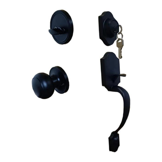
- Page 4 STRUCTURE DIAGRAM AND COMPONENTS Name and Qty Name and Qty Front Handle x 1 Latch A x 1 Lower Latch x 1 Cylinder x 1 Deadbolt Rose x 1 Strike Plate x 1 Back Knob x 1 Strike Plate x 1 Strike Box x 1 Screws x 8 Pin x 1...
- Page 5 INSTALLATION 1. MARK DOOR & BORE HOLES(Please refer to the attached opening diagram.) A: Fold template over edgeof door,mark site 60mm or70mm of holes. B: Bore the Φ54mm andΦ25mm holes through the door. C: Cut out a 58x26x3mm base. 2. INSTALL THE LATCH According to the site of lock holes to adjust the latch for 60mm or 70mm.
- Page 6 NOTE: The cam is pushed fully to the right for 70mm backset.(During the adjustment, keeping two teeth of the cam to forward always.) 3. INSTALL EXTERIOR HANDLE MECHANISM Front Handle Place the front handle with stems and square spindle into the latch as shown.
- Page 7 5. INSTALL THE STRIKES The locking bar is pressed down when the door is closed. MAINTENANCE 1. Do not strike with force to avoid damage to the latch and door frame. 2. If there is dirt, use a dry cloth to remove, do not scrub with chemicals such as dishwashing liquid.
- Page 8 Technical Support and E-Warranty Certificate www.vevor.com/support...
Need help?
Do you have a question about the 19985-SN and is the answer not in the manual?
Questions and answers