Table of Contents
Advertisement
Quick Links
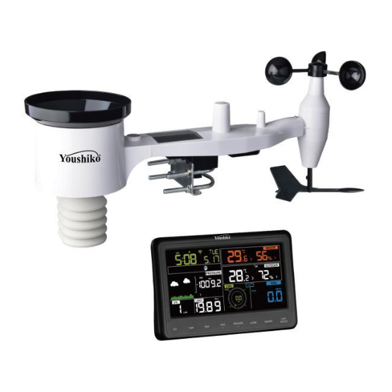
COLOR DISPLAY WIFI WEATHER STATION
Operation Manual
Model: YC9510
Thank you for purchasing this Color Display Wi-Fi Weather Station! This
device provides accurate weather readings and is Wi-Fi capable to stream
data from the weather station to Internet based weather services.
This manual will guide you, step-by-step, through setting up your weather
station and console, and understanding the operation of your weather station.
Use this manual to become familiar with your professional weather station
and save it for future reference.
1
Advertisement
Table of Contents

Subscribe to Our Youtube Channel
Related Manuals for Youshiko YC9510


Summary of Contents for Youshiko YC9510
- Page 1 COLOR DISPLAY WIFI WEATHER STATION Operation Manual Model: YC9510 Thank you for purchasing this Color Display Wi-Fi Weather Station! This device provides accurate weather readings and is Wi-Fi capable to stream data from the weather station to Internet based weather services.
-
Page 2: Table Of Contents
1 Table of Contents 1 Table of Contents ....................2 2 Warnings and Cautions ..................4 3 Unpacking ......................5 4 Features .......................6 5 Set up Guide ....................... 8 5.1 Pre Installation Checkout ................8 5.2 Site Survey ....................8 5.3 Sensor Package Assembly ................9 5.3.1 Install U-bolts and metal plate ............10 5.3.2 Install wind vane ................ - Page 3 6.8.3 Alarm Setting Order ................31 6.9 Max/MinMode ..................... 31 6.9.1 Viewing Max/Min Values..............31 6.9.2 Calibration mode ................33 6.9.3 Calibration Discussion ...............34 6.10 Other Features ..................38 6.10.1 Factory Reset/Clear Memory ............38 6.11 Resynchronize Wireless Sensor ..............38 6.12 Backlight Operation ................39 6.12.1 Tendency indicators .................39 6.12.2 Wireless Signal Strength Indicator ..........
-
Page 4: Warnings And Cautions
2 Warnings and Cautions Warning: Any metal object may attract a lightning strike, including your weather station mounting pole. Never install the weather station in a storm. If you are mounting the weather station to a house or structure, ... -
Page 5: Unpacking
3 Unpacking Open your weather station box and inspect that the contents are intact (nothing broken) and complete (nothing missing). Inside you should find the following: Item Description Display Console Outdoor Sensor Body with built-in: Thermo-hygrometer / Rain Gauge / Wind Speed Sensor/ Wind Direction Sensor, Light and UV sensor, Solar panel Wind speed cups (to be attached to outdoor sensor body) Wind vane (to be attached to outdoor sensor body) -
Page 6: Features
4 Features Color display with 8 touch buttons Calendar (Month/date, 2000-2099 Default Year 2023) Time (hour/minute) Indoor/Outdoor Temperature and Humidity with trend Wind speed, gust speed, and wind direction Absolute and Relative barometric pressure Display rainfall in rate, event, daily, weekly, monthly, yearly and total. - Page 7 Note: The optional YC79 sensor can be purchased separately. If more info needed, please visit our website: www.youshiko.co.uk , Make sure to select the model of the units with the same RF frequency as your gateway (the frequency is different for various countries because of regulations).
-
Page 8: Set Up Guide
5 Set up Guide 5.1 Pre Installation Checkout To complete assembly you will need a Philips screwdriver (size PH0) and a wrench (size M6; included in package). Note: We suggest you assemble all components of the weather station, including console in one location so you can easily test functionality. After testing, place the outdoor sensor package in the desired location. -
Page 9: Sensor Package Assembly
structure, ground, or roof top. 3. Avoid wind and rain obstructions. The rule of thumb is to install the sensor array at least four times the distance of the height of the tallest obstruction. For example, if the building is 20’ or 6.10m tall and the mounting pole is 6’... -
Page 10: Install U-Bolts And Metal Plate
Figure 1: Sensor assembly components Wind speed cups Light sensor and UV sensor Wind vane U-Bolts Thermo- and hygro-meter Battery compartment door sensors Rain collector 10 Reset button Bubble level 11 LED (red) to indicate data transmission Solar panel Table 2: Sensor assembly detailed items 5.3.1 Install U-bolts and metal plate Installation of the U-bolts, which are in turn used to mount the sensor package on a pole, requires installation of an included metal plate to receive... -
Page 11: Install Wind Vane
Loosely screw on the nuts on the ends of the U-bolts. You will tighten these later during final mounting. Final assembly is shown in Figure 3 . Figure 3: U-Bolts and nuts installed The plate and U-Bolts are not yet needed at this stage but doing this now may help avoid damaging wind vane and wind speed cups later on. -
Page 12: Install Wind Speed Cups
5.3.3 Install wind speed cups Push the wind speed cup assembly onto the shaft on the opposite side of the wind vane, as shown in Figure 5 on the left side. Tighten the set screw, with a Philips screwdriver (size PH0), as shown on the right side. Make sure the cup assembly can rotate freely. -
Page 13: Mount Assembled Outdoor Sensor Package
Figure 6: Battery installation diagram Note: If LED does not light up or is on permanently, make sure the battery is inserted the correct way and inserted fully, starting over if necessary. Do not install the batteries backwards as it may permanently damage the outdoor sensor. - Page 14 5.3.5.2 Mounting You can attach a pipe to a permanent structure and then attach the sensor package to it (see Figure 7). The U-Bolts will accommodate a pipe diameter of 1-2 inches (pipe not included). Figure 7: Sensor package mounting diagram Make sure the mounting pipe is vertical, or very close to it.
- Page 15 Note: The orientation to WEST is necessary for two reasons. The most important one is to position the solar panel and light sensor in the most advantageous position for recording solar radiation and charging internal capacitors. Secondly it causes a zero reading for wind direction to correspond to due NORTH, as is customary.
-
Page 16: Reset Button And Transmitter Led
Doing so is also important to avoid false registration of these readings with weather services. 5.3.6 Reset Button and Transmitter LED In the event the sensor array is not transmitting, reset the sensor array. Using a bent-open paperclip, press and hold the RESET BUTTON (see Figure 8) to affect a reset: the LED turns on while the RESET button is depressed, and you can now let go. -
Page 17: Display Console
The frequencies used by the sensors are one of (depending on your location): 433, 868, or 915 MHz (915 MHz for United States). Line of Sight Rating. This device is rated at 300 feet or 100 meter line of sight (under ideal circumstances; no interference, barriers or walls), but in most real-world scenarios, including a wall or two, you will be able to go about 100 feet or 30 meter. - Page 18 Figure 9 Figure 10 Reference Figure 10. (1) Connect the display console power jack to AC power adapter with the included power adapter. (2) Unfold the desk stand and place 5 to 10 feet or 1.5 to 3 meter away from the sensor array.
-
Page 19: Vertical Desk Stand
Figure 11 5.5.1 Vertical Desk Stand The console is best viewed above from a 20 to 30 degree angle. In addition to the fold out desk stand on the back of the display console, the console also includes a vertical desk stand to improve the viewing able on a desk, as shown in Figure 12. -
Page 20: Display Console Operation
6 Display Console Operation 6.1 Screen Display The display console home screen layout is shown in Figure 13. Figure 13: Display Console Screen Layout Time Rain fall Moon phase Outdoor temperature Barometric Pressure Outdoor humidity Weather forecast RF icon UV index Indoor humidity Solar Radiation(Light) Indoor temperature... -
Page 21: Console Initialization
6.2 Console Initialization After the console is connected to AC power, the console will display the software version number two seconds after power up. Figure 14 The console will display all of the LCD segments for three seconds after power up as shown in Figure 15, the indoor conditions will immediately update, and the outdoor sensor array will register within a few minutes. - Page 22 The console has eight buttons for easy operation: Button Description Press and hold to enter the SET mode. In normal display, press this button once will display the MAC address of the device. TEMP. Press to switch between Outdoor Temperature, Wind ...
-
Page 23: Setting Mode
LIGHT / SNOOZE button or waiting for the 30-second time-out to take effect. 6.3 Setting mode Press and hold the SET button for two seconds to enter the SET Mode. To proceed to the next setting, press (do not hold) the SET button. To exit the SET mode at any time, press the LIGHT / SNOOZE button. - Page 24 adjust minute up or down. [SET] Date Format Press [WIND +] to switch between MM-DD (month-day) and DD-MM (day-month). [SET] Year Press [WIND +] or [PRESSURE -] to adjust year up or down. [SET] Month Press [WIND +] or [PRESSURE -] to adjust month up or down.
- Page 25 [SET] Wind Units Press [WIND +] to change of Measure wind units of measure between km/h, mph, knots, m/s and bft. [SET] Rain Press [WIND +] to change Units of rain units of measure Measure between in and mm. Daily rainfall reset time (0:00~23:00) Month rainfall reset time (SUN/MON)
-
Page 26: Barometric Pressure Display
6.4 Barometric Pressure Display 6.4.1 Viewing Absolute vs. Relative Pressure To switch between absolute and relative pressure, press and hold the [PRESSURE -] button for two seconds. Absolute pressure is the measured atmospheric pressure, and is a function of altitude, and to a lesser extent, changes in weather conditions. Absolute pressure is not corrected to sea-level conditions. -
Page 27: Relative Pressure Calibration Discussion
6.4.4 Relative Pressure Calibration Discussion To compare pressure conditions from one location to another, meteorologists correct pressure to sea-level conditions. Because the air pressure decreases as you rise in altitude, the sea-level corrected pressure (the pressure your location would be at if located at sea-level) is generally higher than your measured pressure. -
Page 28: Resetting Rain
Reset total rain, which will auto reset daily, weekly, monthly, yearly, rate, and event rain. For example: Daily rainfall reset time is 8:00 Month rainfall reset time is MON Yearly rainfall reset time is MAY. That the daily rainfall will be reset to 0 at 8:00 every day, the weekly rainfall will be reset to 0 at 8:00 every Monday, the monthly rainfall will be reset to 0 at 8:00 on the 1st each month, the yearly rainfall will be reset to 0 at 8:00 on May 1st every year. -
Page 29: Increments Of Rain Definitions
6.5.3 Increments of Rain Definitions Rain rate or hourly rain is defined as the last 10 minutes of rainfall, multiplied by six (10 minutes x 6 = 1 hour). This is also referred to as instantaneous rain per hour. Rain event is defined as continuous rain, and resets to zero if rainfall ... -
Page 30: Alarm Mode
6.8 Alarm mode 6.8.1 Display of Alarm value Press and release ALARM button to display high alarm Figure 18 Press ALARM button again to display low alarm Figure 19 Note: - Press RAIN button to select display rain rate or rain daily alarm data. - Press WIND/+ button to select display wind or gust alarm data. -
Page 31: Alarm Setting Order
Note: when alert is triggered, the current triggering source icon for time, icon for high value and icon for low value will be flashing, indicating alert is triggered. Note: press ALARM button third time back to normal mode or press LIGHT /SNOOZE button back to normal mode. - Page 32 To view the min values, press the MAX/MIN button again, and the min values will be displayed, as shown in Figure 20 (b). To clear the min values, press and hold the MAX/MIN button while the min values are displayed. To return to normal mode, press the MAX/MIN button again or press LIGHT /SNOOZE button.
-
Page 33: Calibration Mode
6.9.1.3 Display Rain Rate, Daily Rain, Weekly Rain and Monthly Rain Max Values While the max values are displayed as outlined in Section 6.9.1, press the RAIN button once to view the max daily rain, twice to view the max weekly rain, three times to view the max monthly rain, four times to return to the max rain rate. -
Page 34: Calibration Discussion
6.9.2.1 Calibration Order: Indoor temperature offset calibrated (range +/-9F, default: 0 degrees) Indoor humidity offset calibrated (range +/-10%) Outdoor temperature offset calibrated (range +/-9F, default: 0 degrees) Outdoor humidity offset calibrated (range +/-10%) Absolute pressure offset calibrated (range +/-50hpa) ... - Page 35 Parameter Type of Default Typical Calibration Source Calibration Temperature Offset Current Value Red Spirit or Mercury Thermometer (1) Humidity Offset Current Value Sling Psychrometer (2) Offset Current Value Calibrated laboratory grade Barometer barometer Offset Current Value Local airport (3) Barometer Wind Offset Current Value GPS, Compass (4)
- Page 36 (2) Humidity is a difficult parameter to measure electronically and drifts over time due to contamination. In addition, location has an adverse affect on humidity readings (installation over dirt vs. lawn for example). Official stations recalibrate or replace humidity sensors on a yearly basis. Due to manufacturing tolerances, the humidity is accurate to ±5%.
- Page 37 (4) Only use this if you improperly installed the weather station sensor array, and did not point the direction reference to true north. (5) Wind speed is the most sensitive to installation constraints. The rule of thumb for properly installing a wind speed sensor is 4 x the distance of the tallest obstruction.
-
Page 38: Other Features
For example, if the current wind direction is 288, then you’ll need to set the wind direction offset to be: 288-180=108. If the current wind direction is 12, then you’ll need to set the wind direction offset to be: 12+180=190. (6) The rain collector is calibrated at the factory based on the funnel diameter. -
Page 39: Backlight Operation
6.12 Backlight Operation With AC adaptor The backlight can only be continuously on when the AC adapter is permanently on. When the AC adapter is disconnected, the backlight can be temporarily turned on. Press the LIGHT SNOOZE button to adjust the brightness between High, Low and Off. -
Page 40: Wireless Signal Strength Indicator
6.12.2 Wireless Signal Strength Indicator The wireless signal strength displays reception quality. If no signal is lost, the signal strength indicator will display 5 bars. If the signal is lost once, four bars will be displayed, as show in Figure 22. Lost the signal once Received the signal once Figure 22... -
Page 41: Storm Alert
6.12.4 Storm Alert If there is a rapid drop in barometric pressure, the forecast icon will flash. 6.12.5 Weather Forecasting Description and Limitations In general, if the rate of change of pressure increases, the weather is generally improving (sunny to partly cloudy). If the rate of change of pressure decreases, the weather is generally degrading (cloudy, rainy or stormy). -
Page 42: Publishing To Internet Weather Services
7 Publishing to Internet Weather Services Your console is capable of sending your sensor data to select internet-based weather services. The supported services are shown in the table 9 below: Service Website Description Ecowitt https://www.ecowitt.net Ecowitt is a new weather server Weather that can host a bunch of sensors that other services don’t support. -
Page 43: Connecting The Weather Station Console To Wi-Fi
7.1 Connecting the Weather Station Console to Wi-Fi To send weather data to these services you must connect your console to the internet via Wi-Fi. The console can only operate using Wi-Fi when the external power adapter is connected and plugged in! Note: If you are testing the setup with the outdoor sensor package nearby and indoor, you may want to consider connecting to Wi-Fi, but not yet configuring any of the weather services. - Page 44 Start the application and make sure the location permission function is granted (on) when you are running the app for the first time. In case you disabled the location access function for this application, please go to your mobile device settings page and configure it as “on”. The application needs your location to configure weather services.
-
Page 45: Adding And Weather Services
Scroll to the bottom of the screen and press “ Save ” . This will be communicated to the console in a later step. For iOS version: Switch your mobile device to the ad-hoc Wi-Fi network created by your console. It will be named something like “EasyWeatherPro-WIFI” followed by some numbers. -
Page 46: Ecowitt Weather
Figure 24 7.2.1 Ecowitt Weather It’s recommended to use the Ecowitt Weather server to monitor and record your sensors’ data. Configure as follows: On the ecowitt.net uploading page, enable the ON button (displayed blue) and set the uploading interval time. Press Save on the page. - Page 47 Press “Register at ecowitt.net” and finish the registration on the page. Press the “+” button and select enter your email address. Set a password for your ecowitt account. Press Submit. Enter the captcha you received from your email box and press submit. ...
-
Page 48: Viewing Data On Ecowitt.net
It only supports setting the units and language on the WSView Plus app. To use the full settings, please visit the ecowitt website on your browser or on a computer. If you could not register on the WSView Plus app, please go to the website to register and add the device. - Page 49 Graph display List display...
- Page 50 Weather Map Email Alerts...
-
Page 51: Weather Underground
7.3 Weather Underground If you are planning to use wunderground.com you must have an account and register a (new) personal weather station. You may do so on the Wunderground uploading page in the WSView Plus app lication: Press Register at Wunderground.com and finish the registration on the ... - Page 52 3. Select Add New Device. 4. Find Personal Weather Station. Select ‘other’ and click ‘Next’.
- Page 53 5. Select ‘Address’ or ‘Manual’ option, and find your local position. Press ‘Next’. 6. This time you will be asked details about your weather station. Go ahead and fill out the form.
- Page 54 7. After completing the weather station, you will see station ID and key/password. Take note of the PWS identifier (ID) and the password that will be generated for you. Back to the app and input the Station ID and Key. ...
-
Page 55: Viewing Data On Wunderground.com
Note: WU Dashboard shows the data obtained from WU server. This requires that your mobile device can reach the Internet and therefore this is possible even when you are not on your home Wi-Fi network, such as when using cellular data. 7.4 Viewing data on wunderground.com You can also observe your weather station’s data by using the wunderground.com web site. - Page 56 https://itunes.apple.com/us/app/wunderstation-weather-from-your-neighborh ood/id906099986 Weather Underground: Forecast: iOS and Android application for forecasts https://itunes.apple.com/us/app/weather-underground-forecast/id486154808 https://play.google.com/store/apps/details?id=com.wunderground.android.w eather&hl=en...
- Page 57 PWS Weather Station Monitor: View weather conditions in your neighborhood, or even right in your own backyard. Connects to wunderground.com: https://itunes.apple.com/us/app/pws-weather-station-monitor/id713705929...
-
Page 58: Device List
7.5 Device list When on WU Dashboard screen, you can press the “Menu” button (upper right) and select Device List to view all your devices. You can press your device to view or modify the settings. Figure 26 Note: This function requires that your phone and the console is using the same network. -
Page 59: Settings
Figure 27 7.7 Settings You can set your desired display units or default home page for the app by selecting “Settings” on the submenu: Figure 28... -
Page 60: Manage Ecowitt
7.8 Manage Ecowitt Once you created your ecowitt account successful on the WSView Plus app, you may select “Manage Ecowitt” on the submenu to manage your device. You may view your weather station data by pressing your device on this screen:... -
Page 61: Maintenance
8 Maintenance The following steps should be taken for proper maintenance of your station Clean the rain gauge once every 3 months. Rotate the funnel counter-clockwise and lift to expose the rain gauge mechanism, and clean with a damp cloth. Remove any dirt, debris and insects. If bug infestation is an issue, spray the array lightly with insecticide. -
Page 62: Troubleshooting Guide
9 Troubleshooting Guide Look through the following and locate an issue or problem you are experiencing in the left column and read possible solutions in the right column. Problem Solution Outdoor sensor Check that the outdoor transmission LED on the bottom is not reporting to flashing approximately every 16 seconds. - Page 63 Problem Solution outdoor sensor reception on console.” Intermittent There may be a temporary loss of communication due to problems with signal quality issues caused by electrical interference or outdoor sensor other location related factors (obstacles along line of reception on sight).
- Page 64 Problem Solution or both sensors (see section 6.9.3) to adjust to a known good reference temperature. Indoor and The procedure here is that same as for outdoor/indoor Outdoor temperature. The sensors should agree within 10 % (the Humidity do not sensor accuracy is ±...
- Page 65 Problem Solution Confirm that your password (also called: button) is correct. It is the password wunderground.com generated for your station ID. You can also verify it by logging in to wunderground.com and looking it up under “My PWS.” Check your router firewall settings. The console sends data via port 80.
-
Page 66: Glossary Of Common Terms
10 Glossary of Common Terms Term Description Absolute air pressure Absolute air pressure is the air pressure registered on absolute barometric a barometer without regard to altitude. pressure Barometer A barometer is a device that measures the pressure of the air pushing on it—this measurement is called the barometric pressure. - Page 67 Term Description Knots (kn) One knot is equivalent to one nautical mile and is sometimes used to indicate wind speed. An acronym for “Liquid Crystal Display.” This is a common type of display screen used in televisions, computers, watches, and digital clocks. LUX (lx) The unit of illuminance (a measure of the intensity of illumination on a surface) as used in the SI system.
-
Page 68: Specifications
11 Specifications Note: Out of range values will be displayed using “---”: Outdoor sensor Specification Transmission distance in 100 m (330 ft.) open field RF Frequency 433/868/915 MHz depending on location Temperature range -40°C – 60°C (-40°F - 140°F) Temperature accuracy ±... - Page 69 Alkaline batteries under such circumstances. Declaration of Conformity: Youshiko Ltd hereby declares that the product fully complied to applicable guidelines and corresponding standards and requirements of UKCA and other relevant provisions of Directive 1999/5/EC. LIABILITY.
- Page 70 • No part of this manual may be reproduced without written authorization of the manufacturer. Supplied in Box: 1 x Youshiko YC9510 Console with desk stand 1 x Out door 7-in1 Sensor 1 x Instruction manual 1 x Mounting Hardware pack...
- Page 71 1 x Power supply All enquiries: service@youshiko.co.uk Made for Youshiko in PRC...
Need help?
Do you have a question about the YC9510 and is the answer not in the manual?
Questions and answers