Advertisement
Quick Links
738ZplusINT Z-WAVE INTERFACE
MODULE
Installation Guide
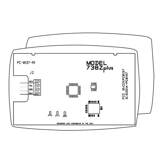
Figure 1: 738ZplusINT Z-Wave
Interface Module
DESCRIPTION
The 738ZplusINT Z-Wave Interface
Module allows DMP panels to
communicate with up to 140
Z-Wave or Z-Wave Plus devices,
such as light controls, light bulbs,
door locks, garage door openers,
and thermostats.
The 738ZplusINT is automatically
recognized by DMP panels, and no
additional programming is required.
Once the module is connected to a
DMP panel, users can immediately
begin adding Z-Wave devices to
their system.
Devices can be remotely controlled
from smart phones using the DMP
Virtual Keypad™ App.
Compatibility
•
DMP XT30INT/XT50INT
Series panels
•
DMP XR150INT/XR550INT
Series panels
•
All Z-Wave and Z-Wave
Plus devices
•
See the Compatibility section for
complete information.
What is Included?
•
738ZplusINT Z-Wave
Interface Module
•
Hardware pack
1
SELECT THE LOCATION
Select a central location for the 738ZplusINT Z-Wave Interface
Module. Keep in mind that at least one Z-Wave Plus device must
be within 65 feet of the module. Most Z-Wave Plus devices act as
repeaters for the signal to create longer and multiple transmission
routes (battery-powered Z-Wave Plus devices do not repeat signals
in order to extend battery life). See Figure 2.
Note: Place the module away from large, metal objects to
avoid interference with the Z-Wave Plus signal.
Office
Living Room
Figure 2: Example Z-Wave Plus Transmission Routes
2
MOUNT THE 738ZplusINT
1.
With the housing cover off, carefully remove the
738ZplusINT's PCB from the housing.
2.
Use the supplied screws to secure the 738ZplusINT housing
against a wall or flat surface. See Figure 3.
Figure 3: 738ZplusINT Housing with Mounting Holes
Dining
Kitchen
Foyer
= Z-Wave Plus Device
Mounting Holes
Control
Panel with
738ZplusINT
Garage
Advertisement

Subscribe to Our Youtube Channel
Related Manuals for DMP Electronics 738ZplusINT


Summary of Contents for DMP Electronics 738ZplusINT
- Page 1 MODULE Installation Guide SELECT THE LOCATION Select a central location for the 738ZplusINT Z-Wave Interface Module. Keep in mind that at least one Z-Wave Plus device must be within 65 feet of the module. Most Z-Wave Plus devices act as...
- Page 2 ADD DEVICES After wiring the 738ZplusINT to the panel, use a DMP keypad to program Z-Wave Plus devices into the panel through the User Menu Z-Wave Setup option. This allows users to add devices through the User Menu or the Virtual Keypad™...
- Page 3 ADDITIONAL INFORMATION LED Operation The 738ZplusINT has three LEDs on the PCB that allow you to determine what type of operation is occurring. See Figure 4 for LED locations. • PTX Green LED - If the light is blinking, then data is being sent to the panel.
- Page 4 738ZplusINT Z-WAVE Certifications Industry Canada: 5251A-PC0137R2 INTERFACE MODULE EN 300 220/489 Specifications Power Requirements Operating Voltage 8 to 14 VDC Current Draw 40 mA Frequency Range 868 MHz Dimensions 4.5”W x 2.75”H x 1.75”D Color White Housing Material Flame retardant ABS Designed, engineered, and I N T R U S I O N •...
Need help?
Do you have a question about the 738ZplusINT and is the answer not in the manual?
Questions and answers