Table of Contents
Advertisement
Quick Links
867 STYLE W LX-BUS
NOTIFICATION MODULE
Installation Guide
BELL ADDRESS
TENS
ONES
MODEL
867
SUPERVISORY ADDR
TENS
ONES
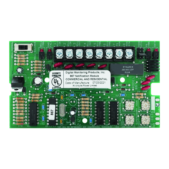
Figure 1: 867 Module
DESCRIPTION
The 867 module provides
one supervised Style W
notification appliance circuit
for powering polarized 12 or
24 VDC fire notification
devices on XR150/XR550
Series panels. The module
connects to the panel
LX‑Bus and provides ground
fault, open, and short
condition supervision on
the notification circuit. The
module has four LEDs to
indicate circuit trouble and
ground fault conditions, as
well as power supply and
data monitoring.
The 867 also has a silence
switch that allows technicians
to disable the module bell
output during service and
maintenance checks.
• XR150/XR550 Series
panels
• 505‑12 Series power
supplies
What is Included?
• One 867 NAC Module
• One Model 308 10k Ohm
Resistor with Leads
• Hardware Pack
1
BELL NORMAL
BELL SILENCE
BELL
TRBL
GND
FAULT
1
BELL
+ IN
2
BELL
- IN
3
BELL
+ OUT
4
BELL
- OUT
5
BELL
TRBL
6
BELL
TRBL
7
PS
MON
8
MON
ATN
RING
STYL
PS
TRBL
DATA
2
MOUNT THE MODULE
The module can be mounted in a DMP enclosure
using the standard 3‑hole mounting pattern.
Refer to Figure 2 as needed during installation.
1. Hold the plastic standoffs against the inside
of the enclosure side wall.
2. Insert the included Phillips head screws
from the outside of the enclosure into the
standoffs. Tighten the screws.
3. Carefully snap the module onto the
standoffs.
Figure 2: Standoff and Module Installation
ADDRESS THE MODULE
For more information about addressing and
switch locations, refer to Table 1 and Figure 4
respectively.
Set the Bell Output Address
Bell Address switches allow you to set an output
number for the module that can be activated by
any panel zone, fire bell output, or burglary bell
output. When activated, the module provides a
programmed bell output for the duration of the
bell cutoff time or until manually silenced by an
authorized user.
Set the Supervisory Zone Address
Supervisory Address switches allow you to
set the zone address for the module, which is
programmed into the panel as a supervisory
zone. A trouble condition on the bell circuit either
causes the panel to display a trouble on the
keypads or trips zone outputs and reports the
trouble to the central station.
The module occupies a single zone address on
the LX‑Bus. For example, on an XR550 Series
panel, a module connected to LX700 with
the switches set to 5, 2 would be Supervisory
Address zone number 752.
1
2
3
Advertisement
Table of Contents

Related Manuals for DMP Electronics 867 W LX-BUS


Summary of Contents for DMP Electronics 867 W LX-BUS
- Page 1 867 STYLE W LX-BUS NOTIFICATION MODULE Installation Guide MOUNT THE MODULE BELL NORMAL The module can be mounted in a DMP enclosure BELL SILENCE BELL TRBL FAULT using the standard 3‑hole mounting pattern. BELL + IN BELL - IN Refer to Figure 2 as needed during installation. BELL + OUT BELL...
- Page 2 XR150 XR550 SERIES SWITCH SERIES TENS ONES LX500 LX500 LX600 LX700 LX800 LX900 Table 1: LX-Bus Addresses SELECT A BELL RING STYLE The 867 module allows you to specify the cadence of the bell output with the Ring Style header. To select a bell ring style, place a jumper across the two appropriate pins on the header as shown in Figure 3.
- Page 3 BELL NORMAL Bell Silence Slide Switch Trouble and Ground Fault LEDs BELL SILENCE BELL TRBL FAULT From 505-12 DC + BELL + IN From 505-12 DC – BELL - IN To Bell Output + BELL + OUT To Bell Output – –...
- Page 4 FCC INFORMATION This device complies with Part 15 of the FCC Rules. Operation is subject to the following two conditions: This device may not cause harmful interference, and 2. this device must accept any interference received, including interference that may cause undesired operation.
Need help?
Do you have a question about the 867 W LX-BUS and is the answer not in the manual?
Questions and answers