Table of Contents
Advertisement
Quick Links
Advertisement
Table of Contents

Related Manuals for Remak VCS

Summary of Contents for Remak VCS
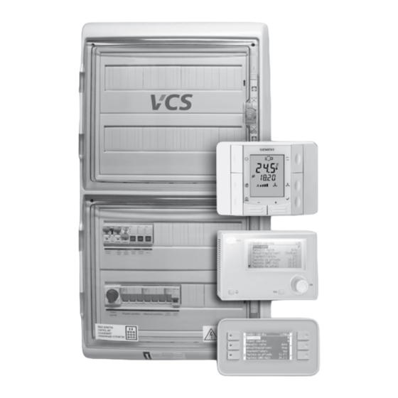
- Page 1 Control units...
-
Page 2: Table Of Contents
VCS control units must be installed and used only in accor- of components concerning their suitability for a given dance with this documentation. Without the manufactu- application. -
Page 3: Equipment Characteristics, Box Design
IP54 when the The indoor units come in either painted steel or plastic (not door is closed and IP20 when the door is open. The VCS in for SKFM) boxes - both with transparent doors. -
Page 4: Control
Google Android (v. 4.1 and higher) or Apple iOS (v. 12.2 and higher), or application for PC with Windows 64bit. The core of the VCS system is created by a powerful Siemens c) AHU unit operation visualization Climatix series PLC controller. The control unit can be equipped Monitoring and operation using the device’s technological... -
Page 5: Poer Part, Design
Figure 7 – Component wiring (example) Connecting terminals Design The design of the M&C system, specifically the configuration of the control unit and its box, is carried out in the REMAK design software. Table 1 – The dimensions of the main VCS boxes... -
Page 6: Documentation And Safety Measures
(for communication with the manufacturer). Any changes or modifications to individual components of the VCS control unit which could affect its safe and proper Documentation functioning are forbidden. The air-handling equipment configuration and documenta-... -
Page 7: Location And Installation
Transport and Storage before installation. Before Installation VCS control units are packed in cardboard boxes or installed in the corresponding air-handling unit section, if they are integrated into the air-handling unit. Measures for handling fragile goods must be taken when handling the unit. -
Page 8: Commissioning
For a general overview of parameters available in the menu applicable local wiring standards and regulations. Before put- and access authorization of users, refer to the chapter VCS ting the unit into operation, an initial wiring inspection must – Parameter Overview and Default Factory Settings. For the be performed in accordance with the national regulations. -
Page 9: Frequency Inverter Connection
The sensor must be situated in a representative place The first device, i.e. the master controller, terminal resistor within the flue gas installation. setting is performed using the software (ensured by REMAK in the factory). -
Page 10: Control And Protection Functions
RHR motor address =11 The data points of all frequency inverters for communica- tion with the Modbus bus must be set in accordance with the VCS control unit: • Baud rate (9600 Bd – pre-set) • Parity (none – pre-set) •... - Page 11 If a serious failure occurs, the unit will be switched to the STOP mode, and it can only be restarted after the The VCS control unit enables automatic control of the following failure has been removed and the operator's interference.
- Page 12 8°C (factory settings), the following Electric heater control in the REMAK unit is doubled – the protection actions will be immediately taken regardless of the heater thermostat failure signal is simultaneously sent to the controller and auxiliary module.
- Page 13 The heat pump control is equipped with an outdoor tempera- The gas section (chamber) temperature for protection and safety functions outside the VCS control system is picked up ture-dependent blocking. The blocking alert is only informative by the ESD3J triple electronic safety thermostat (located on and is not a failure state.
- Page 14 0–10 V control signal. stay open until the ice build-up melts from the heat exchanger. A VCS can be configured for (progressive) control of up to three pressure loss sensor or a CAP 3M capillary probe can also be used inverter condensing units (including their occasional swapping in some cases.
- Page 15 This function is applied when the main heater output is not suf- can be performed by the VCS control unit or by an autonomous ficient (e.g. when water heating is shut down during transition control (e.g., integrated into the humidifier).
- Page 16 Fan Speed Compensation In cases where a heating cable is used as a frost protection for The VCS control unit system enables the pre-set fan speed to be condensate drain siphons, the control unit ensures its switching adjusted depending on the air temperature, air quality or mixing according to the outside temperature.
- Page 17 Fan speed is controlled depending on the desired air flow rate /h). The air flow rate (air pressure in the diffuser recalcu- The VCS control unit enables either software or manual air output lated to the air flow rate using the "k-factor") is measured by a control, i.e.
- Page 18 /h. This value is then entered rooms as the maximum range of the sensor in the VCS using HMI. Note: When commissioning the system, it is necessary to Note: In AC, the "Max. Air Flow Rate" is stated for the fan as- perform the settings and regulation of the device (PID con- semblies.
-
Page 19: Basic Operating Modes
Operating states on the user's option. All the operating modes and their correlation There are three operating states defined for VCS control units are shown in the figure # 10 - "Operating modes". (Stop, Run, Auto): The current operating mode can be monitored through the HMI Stop –... -
Page 20: Temperature And Time Modes
Additional Operating Modes Heating Single-speed motor fans: >> Stage 1 Activation Two-speed motor fans: When the following conditions are fulfilled simultaneously: >> Stage 1 / Stage 2 < T All five-stage controlled fans: Once the t time interval has elapsed >> Stage 1 / Stage 2 / Termination Stage 3 / Stage 4 / Stage 5 If the following condition is fulfilled:... - Page 21 These modes interact, applying the system priorities. At any time, the air-handling operation is always controlled by the time The VCS control unit system offers the possibility to maintain schedule with the highest priority provided that it has an active the controlled room or supply air temperature using two user time interval for that moment.
-
Page 22: Hmi-Sg
5 °C to 40 °C Relative humidity < 85 % Recovery and mixing sequences – energy savings Warning: To avoid unintentional unit start-up, the master switch must be Alarm switched off and locked when repairing the VCS unit. Data point editing... - Page 23 The maximum distance between the control unit and room controller is up to 700 m. Factory set default rights to access the VCS control unit using the HMI controller: HMI-SG controllers are connected to the master controller in series and wiring is always performed to one point.
- Page 24 Control (HMI-SG) Communication Settings Data Point List Access and Editing An overview of the structure of parameters accessible via the Once the HMI-SG controller has been connected to the control HMI-SG controller is available in the List of Data Points upon unit, the communication between both devices will be set logging in using the appropriate access right level.
- Page 25 HMI-SG controller's operating mode. System Date and Time Settings Here, the actual VCS system date and time can be set – First Control Unit Start-Up Using HMI-SG Controller these setting are required for correct functioning of the time 1) Press the Plus (T5), Minus (T4) and Mode (T8) buttons schedule programs.
- Page 26 Operating Screen (Examples) connected to the device failure detection inputs (incorrect state of the contact) occurs, the VCS control unit will au- After making the HMI-SG controller a service controller, it is tomatically put out an alarm in accordance with an internal possible to change the control unit settings.
- Page 27 Use the Program (T3) or Presence (T2) buttons to exit the Quick Menu. Only those values which are included within the given version of the VCS unit are displayed. Briefly press the OK (T6) button to display the values listed...
- Page 28 Control (HMI-SG) List of Data Points, Factory Settings Additional Operating Modes and Function Settings Warning: Additional operating modes and functions can be activated The device parameters are structured and made available to in the List of Data Points in the section Settings – Additional users in accordance with their user roles (access levels).
-
Page 29: List Of Data Points Hmi-Sg
Control units VCS List of Data Points (HMI-SG controller) Menu HMI-SG Factory Settings Parameter Notation Reading Value Meaning code level code level Monitor Temperature °C Temperature in the inlet °C Temperature in the room 1 °C Temperature in the room 2 °C... - Page 30 List of Data Points (HMI-SG controller) Menu HMI-SG Factory Settings Parameter Notation Reading Value Meaning code level code level Pre-heating function of water heating Water cooler pump state Evaporator cooling stage Stage 1 Stage 2 Inverter cooling stage (inverter) Inverter cooling stage (step1+inverter) Heat pump operating state out of operation cooling...
- Page 31 Control units VCS List of Data Points (HMI-SG controller) Menu HMI-SG Factory Settings Parameter Notation Reading Value Meaning code level code level Calculated absolute inlet air humidity g/kg Calculated inlet air humidity enthalpy kJ/kg Calculated absolute room air humidity g/kg...
- Page 32 List of Data Points (HMI-SG controller) Menu HMI-SG Factory Settings Parameter Notation Reading Value Meaning code level code level Stage 3 Stage 4 Stage 5 Temperature mode setting "Higher" Comfort (Ext. control 2 contacts) Economy Fans - Modbus Regulation limits Inlet fan output St1 setting % (m3/h, Pa) Inlet fan output St1 setting (násobitel 10)
- Page 33 Control units VCS List of Data Points (HMI-SG controller) Menu HMI-SG Factory Settings Parameter Notation Reading Value Meaning code level code level + 1 stage + 2 stages + 3 stages + 4 stages For operating stage St1 - 4 stage...
- Page 34 List of Data Points (HMI-SG controller) Menu HMI-SG Factory Settings Parameter Notation Reading Value Meaning code level code level Transition time-out from speed 2 to speed 1 Inlet temperature limitation Minimum inlet air temperature °C Maximum inlet air temperature °C Additional operating modes, functions Outdoor temperature depend- ent fan speed compensation...
- Page 35 Control units VCS List of Data Points (HMI-SG controller) Menu HMI-SG Factory Settings Parameter Notation Reading Value Meaning code level code level room temp. sensor 1 room temp. sensor 2 HMI-SG 1 controller HMI-SG 2 controller Control signal characteristic Control signal 0-10 V or 2-10 V, heating...
- Page 36 List of Data Points (HMI-SG controller) Menu HMI-SG Factory Settings Parameter Notation Reading Value Meaning code level code level Regulation additional fan none 1 stage 5 stage (TRN) V100 2xV10 2xV100 Heating water electric Heat pump variation A variation B Type of gas heating 1 stage 2 stage...
- Page 37 Control units VCS List of Data Points (HMI-SG controller) Menu HMI-SG Factory Settings Parameter Notation Reading Value Meaning code level code level Cooling initial point (outdoor temperature) °C Cooling end point (outdoor temperature) °C Maximum cooling compensation (required value) Heating initial point (outdoor temperature) °C...
- Page 38 List of Data Points (HMI-SG controller) Menu HMI-SG Factory Settings Parameter Notation Reading Value Meaning code level code level Signal inversion for heat pump, cooling Switching to special signal 0-10V (Daikin) The difference between the demand and the actual signal to determine St2 Time it takes for the signal to transition from 0 to 100% Voltage signal for heating demand (Toshiba) 3,25...
- Page 39 Control units VCS List of Data Points (HMI-SG controller) Menu HMI-SG Factory Settings Parameter Notation Reading Value Meaning code level code level Start-up sequence delay Gas heating Cooling sequence enabling without cooling with cooling Minimum burner run time Minimum burner downtime...
- Page 40 List of Data Points (HMI-SG controller) List of Data Points (HMI-SG controller) Menu HMI-SG Factory Settings Parameter Notation Reading Value Meaning code level code level Humidification power Calculated current desired humidity value in the cascade Dehumidification Dehumidification required relative value - Comfort %r.H.
- Page 41 Control units VCS List of Data Points (HMI-SG controller) Menu HMI-SG Factory Settings Parameter Notation Reading Value Meaning code level code level Proportional factor Integrating factor Derivative factor Electric reheating Proportional factor Integrating factor Derivative factor Electric pre-heating Proportional factor...
- Page 42 List of Data Points (HMI-SG controller) Menu HMI-SG Factory Settings Parameter Notation Reading Value Meaning code level code level Integrating factor Derivative factor Constant flow (pressure) regulation - supply Proportional factor Integrating factor Derivative factor Constant flow (pressure) regulation - exhaust Proportional factor Integrating factor Derivative factor...
- Page 43 Control units VCS List of Data Points (HMI-SG controller) Menu HMI-SG Factory Settings Parameter Notation Reading Value Meaning code level code level Factory settings Data point recovery (factory settings) User settings Data point saving (user settings) without saving with saving...
- Page 44 List of Data Points (HMI-SG controller) Menu HMI-SG Factory Settings Parameter Notation Reading Value Meaning code level code level Enable settings network connection over HMI SG passive active System settings - room unit Transition to time program delay Byte address, Diagnostic mode – byte address Alarm mode only after alarm constantly...
-
Page 45: List Of Failures Hmi-Sg
Control units VCS List of Failures (HMI-SG controller) Failure Failure Causes Description Reduced dehumidi- Reduced dehumidification capacity (pool unit) - Informative notification fication capacity Heat pump defrost Informative fault. During the defrosting of the heat pump, the air han- dling unit is stopped. Subsequently, it is automatically restarted. - Page 46 List of Failures (HMI-SG controller) (continuation) Failure Failure Causes Description Heat pump - Informational notification - operation of the heat pump blocked due to out- is blocked due to outdoor temperature door temperature Heat pump Fault in the heat pump - contact issue Humidification Humidifier fault - contact issue.
- Page 47 Control units VCS List of Failures (HMI-SG controller) (continuation) Failure Failure Causes Description Electric heating Fault in the electric heating - thermostat Electric reheating Fault in the electric reheating - thermostat Water heater Fault in the water heating pump - contact issue...
-
Page 48: Remak Mobile App
Figure 24 – mobile app GUI mobile data to connect to the Internet. Mobile applications such as HMI to VCS serve as a user-friendly driver for basic HVAC control - triggering desired mode (+ switching off), setting (user-friendly parameters only) and simple operation overview (feedback). -
Page 49: Hmi-Dm, Hmi-Tm
HMI-DM (HMI-TM) control devices ensure communication Figure 26 – HMI-DM cotroller between the VCS control unit and the user. They are intended for air-handling device control, handling and service. The HMI control device can be connected to the POL4xx or POL6xx Info controllers. - Page 50 HMI-DM, HMI-TM Figure 27 – Installation on a Wall Table 2 – Function Buttons Button Activity Description (Name) - Scrolling the list upwards Press - Increases the parameter value - Hold this button longer than 1.5 s to speed up the Hold list scrolling upwards - Increases the parameter...
- Page 51 Control units VCS HMI-DM, HMI-TM Value Settings Display Layout If the description and value of the parameter is highlighted on Figure 29 – LCD isplay the line, the highlighted value can be changed. Turn the knob (or use the Up and Down buttons) to select the line.
-
Page 52: Hmi@Web
The PC must be equipped with an Ethernet network card with using local controls, including the possibility of configuring address allocation by a DHCP server. the RJ-45 connector, or connected to the LAN network - VCS with HMI@Web controller can be connected directly to (one) Notice PC or integrated into the LAN, resp. - Page 53 IP address under the " u LAN Connection" section (as described in step 4: Activation). Always restart VCS unit after assigning a new IP address – the new setting is applied after restart. Attention! Always consult with the network administrator before connecting VCS with HMI@Web to the internal LAN network.
- Page 54 HMI@Web 3rd Step: Setting the HMI@Web server for Connection Figure 37 – The home screen The HMI@Web web server controller can be configured from the web interface (the same one which serves for normal operation of the system). Enter the following IP address http://192.168.1.199 in the address field in the web browser and confirm with the "Enter"...
- Page 55 PC so Internet Integration that they are compatible with VCS (controller) (respectively By connecting the VCS system to the local network via the LAN); the HMI@Web controller with the modified setting can above-mentioned setting of the IP address and authorization be alternatively connected to the LAN.
- Page 56 HMI@Web Proxy server Figure 40 – VCS control unit on the WAN network If it is about accessing within the LAN, please contact the LAN/PC administrator for PC configuration. HMI@Web Environment Description HMI@Web The Web controller HMI@Web is controlled using the fol-...
- Page 57 Control units VCS HMI@Web Basic settings for operating In the weekly time schedule, you can also set a day for the exception time schedule. Each day of the week can have HMI@Web control - Recap a maximum of 6 possible time changes and programmed The basic setup of HMI@Web control for the service team states.
-
Page 58: Ahu Unit Operation Visualisation
Current modes The VCS control unit is equipped with a web server running the VCS Visualization. All you have to do is connect the VCS unit to Temperatures the LAN / WAN network and then connect to the VCS control Humidity unit using a web browser. -
Page 59: Other Control - External Control
External control Remote Signalling This enables the control unit to be connected to other technol- The VCS Control unit can optionally be equipped ogy using single- or two-contact control. The Auto operating with one or two outputs for remote signalling. -
Page 60: Pool Units - Descriptioon Of Contro
POOL UNITS – description of control The VCS also allows the control of air-conditioning units Temperature control designed to ventilate swimming pools (swimming pools, water For pool units, room temperature control with limitation of parks, rehabilitation complexes with water procedures, etc.). - Page 61 Control units VCS POOL UNITS – description of control Set the time schedule for the day of the week with integrated mixing) Additionally, over the standard, following is supplemented: Warning: In the time mode, the first basic power stage must when activating this bypass, the inlet/outlet dampers are be set: ÚsporSt1;...
- Page 62 POOL UNITS – operation modes Economy operation mode Comfort mode The amount of fresh air supplied (or mixing) during operating In fully recirculating mode - without the need for dehumidi- hours depends on the current microclimate conditions (hu- fication - the unit provides air heating in the swimming pool midity) in the ventilated space and the set hygiene minimum.
- Page 63 If the integrated cooling compressor unit is used in the air handling unit supplied with the VCS, the PLC for controlling the integrated cooling is usually installed in the VCS and signalled to the Climatix main controller.
-
Page 64: Unit Activation
(terminals) ling the performance of the integrated cooling compressors in are evaluated by the VCS unit, respectively by the controller. If a the air handling unit, or for controlling the electronic expansion... - Page 65 To operate properly, (terminals), i.e. between the feed conductor and terminal. the VCS system requires all sensors according the specifica- Therefore, it is necessary to ensure proper tightening of the tion to be operative.
-
Page 66: Troubleshooting
Troubleshooting, Spare Parts and Service Spare Parts and Service Troubleshooting Spare parts are not included in the VCS unit delivery. When performing any handling or troubleshooting of the air- If any spare parts are needed, they can be ordered from the handling device, the power supply of the entire distribution manufacturer or regional distributor. - Page 67 REMAK a. s., Zuberská 2601, Rožnov pod Radhoštěm, Czech Republic These Installation and Operating Instruc- Warning tions are the sole property of REMAK a. s. Changes reserved. The manufacturer reserves the right to make changes and Issued: 19. 5. 2023 amend the documentation due to technical innovations and changes to legislation without prior notice.
- Page 68 REMAK a.s. Zuberská 2601, 756 61 Rožnov pod Radhoštěm, tel.: +420 571 877 778, fax: +420 571 877 777, email: remak@remak.eu, internet: www.remak.eu...
Need help?
Do you have a question about the VCS and is the answer not in the manual?
Questions and answers