
Subscribe to Our Youtube Channel
Related Manuals for DFI CMS330-Q470E/H420E


Summary of Contents for DFI CMS330-Q470E/H420E
- Page 1 CMS330-Q470E/H420E microATX Industrial Motherboard User’s Manual ver.1_-_7-1321_23-15...
- Page 2 Copyright FCC and DOC Statement on Class B This publication contains information that is protected by copyright. No part of it may be repro- This equipment has been tested and found to comply with the limits for a Class B digital duced in any form or by any means or used to make any transformation/adaptation without the device, pursuant to Part 15 of the FCC rules.
-
Page 3: Table Of Contents
Table of Contents USB Configuration ......................44 CSM Configuration ......................45 Network Stack Configuration..................46 Chapter 1 - Introduction........................ 6 USB Power Control ......................46 Specifications ......................... 6 Chipset ..........................47 Features ..........................8 Graphics Configuration ....................47 Block Diagram ........................9 PEG Port Configuration ....................48 PCH-IO Configuration ....................49 Chapter 2 - Hardware Installation ....................10 PCI Express Configuration ....................49... - Page 4 About this Manual Static Electricity Precautions This manual can be downloaded from the website. It is quite easy to inadvertently damage your PC, system board, components or devices even before installing them in your system unit. Static electrical discharge can damage computer The manual is subject to change and update without notice, and may be based on editions that components without causing any signs of physical damage.
- Page 5 Before Using the System Board About the Package When installing the system board in a new system, you will need at least the following internal The package contains the following items. If any of these items are missing or damaged, components.
-
Page 6: Chapter 1 - Introduction
Chapter 1 INTRODUCTION Chapter 1 - Introduction ® Graphics Controller Intel HD Gen 9 Graphics Feature OpenGL 4.5, DirectX 12, OpenCL 2.1 HW Decode: AVC/H.264, MPEG2, VC1/WMV9, JPEG/ X Specifications MJPEG, HEVC/H265, VP8, VP9 HW Encode: MPEG2, AVC/H264, JPEG, HEVC/H265, VP8, System Processor 10th Generation Intel... - Page 7 Chapter 1 INTRODUCTION Internal I/O Serial 5 x RS-232 (2.54mm pitch) (Up to 9 x RS-232, MOQ required) 2 x USB 3.2 Gen 1 Q470E: 4 x USB 2.0 (2.54mm pitch, Colay vertical Type A, opt.: MOQ required) H420E: 2 x USB 2.0 (2.54mm pitch, Colay vertical Type A, opt.: MOQ required) 1 x USB 2.0 Vertical Type A (Q470E default SKU) Audio...
-
Page 8: Features
Chapter 1 INTRODUCTION X Features Watchdog Timer PCI Express The Watchdog Timer function allows your application to regularly “clear” the system at the set PCI Express is a high bandwidth I/O infrastructure that possesses the ability to scale speeds time interval. If the system hangs or fails to function, it will reset at the set time interval so that by forming multiple lanes. -
Page 9: Block Diagram
Chapter 1 INTRODUCTION X Block Diagram Channel A DDR4 2400/2666/2933MHzDIMM Channel A PTN3355 DDR4 2400/2666/2933MHzDIMM (Q470E) Channel B DP++ LGA 1200 DDR4 2400/2666/2933MHzDIMM Channel B HDMI DDR4 2400/2666/2933MHzDIMM (Q470E) ASM1442K PCIe x16 (Gen3) PCIe x16 1x DMI 3.0 GLAN I211AT LAN 1 PCIe x1 IT8893E... -
Page 10: Chapter 2 - Hardware Installation
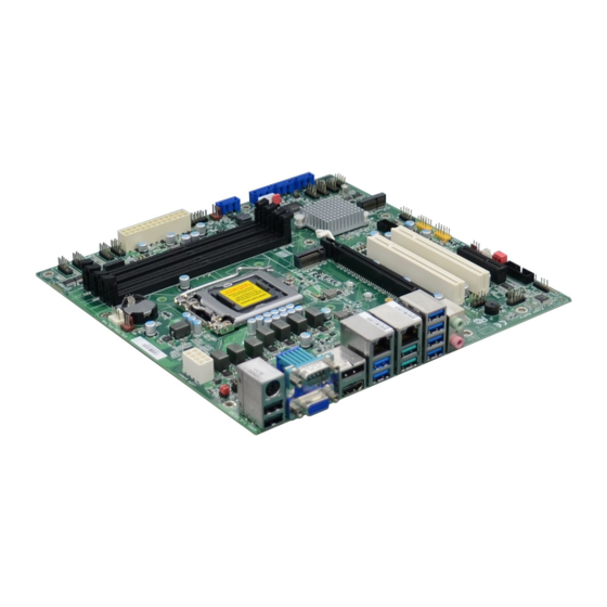
Chapter 2 HARDWARE INSTALLATION Chapter 2 - Hardware Installation X Board Layout Note: Some components are optional and only available upon request. JP4/2/3/1 SYS FAN1 CPU FAN1 (top to bottom) DDR4_3 DDR4_4 USB 7/8 (USB 2.0) +12V Power Important: Battery Electrostatic discharge (ESD) can damage your board, processor, disk drives, add-in boards, and other components. -
Page 11: System Memory
Chapter 2 HARDWARE INSTALLATION X System Memory System Memory Installing the DIMM Module JP4/2/3/1 SYS FAN1 CPU FAN1 (top to bottom) DDR4_3 DDR4_4 USB 7/8 (USB 2.0) +12V Power Before installing the memory module, please make sure that the following safety cautions are Battery well-attended. -
Page 12: Removing The Dimm Module
Chapter 2 HARDWARE INSTALLATION System Memory Installing the DIMM Module System Memory Removing the DIMM Module Please follow the steps below to install the memory card into the socket. Please follow the steps below to remove the memory card from the socket. Step 1: Press the eject tabs at both ends of the socket outward and downward to release them from Step 1:... -
Page 13: Cpu
Chapter 2 HARDWARE INSTALLATION X CPU Installing the CPU Fan and Heat Sink The CPU must be kept cool by using a CPU fan with heat sink. Without sufficient air circula- tion across the CPU and heat sink, the CPU will overheat damaging both the CPU and system board. -
Page 14: Jumper Settings
Chapter 2 HARDWARE INSTALLATION X Jumper Settings DIO Power CLEAR CMOS Data JP4/2/3/1 SYS FAN1 CPU FAN1 (top to bottom) DDR4_3 DDR4_4 JP4/2/3/1 USB 7/8 SYS FAN1 CPU FAN1 (top to bottom) (USB 2.0) DDR4_3 DDR4_4 +12V Power USB 7/8 Battery (USB 2.0) +12V Power... -
Page 15: Com1/Com2 Rs232/422/485 Select
Chapter 2 HARDWARE INSTALLATION Jumper Settings „ JP1/JP2 2 4 6 2 4 6 2 4 6 COM1/COM2 RS232/422/485 Select 1 3 5 1 3 5 1 3 5 1-3, 2-4 On: 3-5, 4-6 On: 3-5, 2-4 On: RS232 (default) RS422 Full Duplex RS485 JP4/2/3/1... -
Page 16: Com1 Rs232 Power Select
Chapter 2 HARDWARE INSTALLATION Jumper Settings COM1 RS232 Power Select JP4/2/3/1 SYS FAN1 CPU FAN1 (top to bottom) DDR4_3 DDR4_4 USB 7/8 (USB 2.0) (COM 1) +12V Power Battery LGA 1200 HDMI power LAN1 USB 1/2 (USB 3.2 Gen 2) Standby Power LAN2... -
Page 17: At/Atx Mode - Jp26
Chapter 2 HARDWARE INSTALLATION Jumper Settings AT/ATX Mode - JP26 JP4/2/3/1 SYS FAN1 CPU FAN1 (top to bottom) DDR4_3 DDR4_4 USB 7/8 (USB 2.0) +12V Power Battery LGA 1200 HDMI power LAN1 USB 1/2 1-2 On: (USB 3.2 Gen 2) Standby GND (default) Power... -
Page 18: Usb Power Control - Jp25
Chapter 2 HARDWARE INSTALLATION Jumper Settings USB Power Control - JP25 JP4/2/3/1 SYS FAN1 CPU FAN1 (top to bottom) DDR4_3 DDR4_4 USB 7/8 (USB 2.0) +12V Power Battery LGA 1200 HDMI power LAN1 USB 1/2 (USB 3.2 Gen 2) Standby 1-2 On: Power 5VDU (default) -
Page 19: Rear I/O Ports
Chapter 2 HARDWARE INSTALLATION X Rear I/O Ports USB 3.2 LAN 1 LAN 2 Gen 1 COM 1 DP++ Line-out Mic-in USB 2.0 HDMI USB 3.2 USB 3.2 Gen 2 Gen 1 The rear panel I/O ports consist of the following: •... -
Page 20: Usb Ports
Chapter 2 HARDWARE INSTALLATION Rear I/O Ports „ USB 2.0 Headers (USB 9/10/11/12) USB Ports Assignment Assignment JP4/2/3/1 USB 7/8 (USB 2.0 ) SYS FAN1 CPU FAN1 (top to bottom) DDR4_3 DDR4_4 Data- Data- USB 7/8 (USB 2.0) +12V Power Battery Data+ Data+... -
Page 21: Graphics Interfaces
Chapter 2 HARDWARE INSTALLATION Rear I/O Ports Graphics Interfaces DP++ Port The DP++ port which carries both digital audio and video signals is used to connect a LCD The display ports consist of the following: monitor or a digital TV that has the DP++ port. HDMI Port •... -
Page 22: Rj45 Lan Ports
Chapter 2 HARDWARE INSTALLATION Rear I/O Ports Rear I/O Ports RJ45 LAN Ports Audio JP4/2/3/1 (top to bottom) SYS FAN1 CPU FAN1 DDR4_3 DDR4_4 USB 7/8 (USB 2.0) JP4/2/3/1 +12V Power SYS FAN1 CPU FAN1 (top to bottom) Battery DDR4_3 DDR4_4 USB 7/8 (USB 2.0) -
Page 23: Com 1
Chapter 2 HARDWARE INSTALLATION Rear I/O Ports COM 1 JP4/2/3/1 SYS FAN1 CPU FAN1 (top to bottom) COM1 DDR4_3 DDR4_4 USB 7/8 (USB 2.0) +12V Power Battery LGA 1200 HDMI power LAN1 USB 1/2 (USB 3.2 Gen 2) Standby Power LAN2 USB 3/4 (USB 3.2 Gen 1) -
Page 24: Internal I/O Connectors
Chapter 2 HARDWARE INSTALLATION X Internal I/O Connectors Internal I/O Connectors Digital I/O Connector (2.0mm pitch) SATA (Serial ATA) SATA Pin Assignment „ JP4/2/3/1 JP4/2/3/1 SYS FAN1 CPU FAN1 SYS FAN1 CPU FAN1 (top to bottom) (top to bottom) DDR4_3 DDR4_4 DDR4_3 DDR4_4... -
Page 25: Com (Serial) Ports
Chapter 2 HARDWARE INSTALLATION Internal I/O Connectors COM (Serial) ports Connecting External Serial Ports JP4/2/3/1 (top to bottom) SYS FAN1 CPU FAN1 DDR4_3 DDR4_4 USB 7/8 (USB 2.0) Your COM port may come mounted on a card-edge bracket. Install the card-edge bracket to +12V Power Battery an available slot at the rear of the system chassis then insert the serial port cable to the COM... -
Page 26: Cooling Fan Connectors
Chapter 2 HARDWARE INSTALLATION Internal I/O Connectors Internal I/O Connectors Cooling Fan Connectors Power Connector System Fan CPU Fan „ ATX 8-pin Power Connectors JP4/2/3/1 SYS FAN1 CPU FAN1 (top to bottom) DDR4_3 DDR4_4 USB 7/8 (USB 2.0) +12V +12V Power Battery 12 24 +3.3V... -
Page 27: Front Panel
Chapter 2 HARDWARE INSTALLATION Internal I/O Connectors Front Panel JP4/2/3/1 SYS FAN1 CPU FAN1 (top to bottom) DDR4_3 DDR4_4 USB 7/8 (USB 2.0) +12V Power Battery LGA 1200 Front Panel Connector „ HDMI power PWR-LED ATX-SW LAN1 USB 1/2 (USB 3.2 Gen 2) Standby Power LAN2... -
Page 28: Lan Led Connector
Chapter 2 HARDWARE INSTALLATION Internal I/O Connectors Internal I/O Connectors LAN LED Connector S/PDIF Connector JP4/2/3/1 SYS FAN1 CPU FAN1 (top to bottom) JP4/2/3/1 SYS FAN1 CPU FAN1 (top to bottom) DDR4_3 DDR4_4 USB 7/8 DDR4_3 DDR4_4 (USB 2.0) USB 7/8 (USB 2.0) +12V Power Battery... -
Page 29: Smbus Connector
Chapter 2 HARDWARE INSTALLATION Internal I/O Connectors Internal I/O Connectors SMBus Connector LPC Connector „ LPC Connector JP4/2/3/1 JP4/2/3/1 (top to bottom) SYS FAN1 CPU FAN1 SYS FAN1 CPU FAN1 (top to bottom) DDR4_3 DDR4_4 DDR4_3 DDR4_4 USB 7/8 USB 7/8 (USB 2.0) (USB 2.0) +12V Power... -
Page 30: Chassis Intrusion Connector
Chapter 2 HARDWARE INSTALLATION Internal I/O Connectors Internal I/O Connectors Internal I/O Connectors Chassis Intrusion Connector InnoAGE HDR1 (JP24) JP4/2/3/1 SYS FAN1 CPU FAN1 JP4/2/3/1 (top to bottom) SYS FAN1 CPU FAN1 (top to bottom) DDR4_3 DDR4_4 JP4/2/3/1 DDR4_3 DDR4_4 USB 7/8 (top to bottom) SYS FAN1 CPU FAN1... -
Page 31: Expansion Slots
Chapter 2 HARDWARE INSTALLATION Internal I/O Connectors Internal I/O Connectors Expansion Slots Expansion Slots Installing the M.2 Module Before installing the M.2 module into the M.2 socket, please make sure that the following safety cautions are well-attended. JP4/2/3/1 1. Make sure the PC and all other peripheral devices connected to it has been powered SYS FAN1 CPU FAN1 (top to bottom) PCIe 1 (PCIe x16) -
Page 32: Battery
Chapter 2 HARDWARE INSTALLATION Internal I/O Connectors Expansion Slots Internal I/O Connectors Battery Please follow the steps below to install the card into the socket. JP4/2/3/1 SYS FAN1 CPU FAN1 (top to bottom) DDR4_3 DDR4_4 USB 7/8 (USB 2.0) +12V Power „... -
Page 33: Chapter 3 - Bios Settings
Chapter 3 Chapter 3 BIOS SETTINGS BIOS SETTINGS Chapter 3 - BIOS Settings Legends X Overview The BIOS is a program that takes care of the basic level of communication between the CPU Keys Function and peripherals. It contains codes for various advanced features found in this system board. The BIOS allows you to configure the system and save the configuration in a battery-backed Right / Left arrow Move the highlight left or right to select a menu... -
Page 34: Main
Chapter 3 Chapter 3 BIOS SETTINGS BIOS SETTINGS X Main X Advanced The Main menu is the first screen that you will see when you enter the BIOS Setup Utility. The Advanced menu allows you to configure your system for basic operation. Some entries are defaults required by the system board, while others, if enabled, will improve the performance of your system or let you set some features according to your preference. -
Page 35: Rc Acpi Configuration
Chapter 3 Chapter 3 BIOS SETTINGS BIOS SETTINGS Advanced Advanced RC ACPI Configuration CPU Configuration Aptio Setup Utility - Copyright (C) 2021 American Megatrends, Inc. Aptio Setup Utility - Copyright (C) 2021 American Megatrends, Inc. Advanced Advanced CPU Configuration When enabled, a VMM can RC ACPI Configuration Enable or disable System utilize the additional hard-... -
Page 36: Power & Performance
Chapter 3 Chapter 3 BIOS SETTINGS BIOS SETTINGS Advanced Advanced Power & Performance PCH-FW Configuration Aptio Setup Utility - Copyright (C) 2021 American Megatrends, Inc. Aptio Setup Utility - Copyright (C) 2021 American Megatrends, Inc. Advanced Advanced ME State [Enabled] When Disabled ME will be Power &... - Page 37 Chapter 3 Chapter 3 BIOS SETTINGS BIOS SETTINGS Advanced PCH-FW Configuration Advanced PCH-FW Configuration ► AMT Configuration ► AMT Configuration ► Secure Erase Configuration Aptio Setup Utility - Copyright (C) 2021 American Megatrends, Inc. Aptio Setup Utility - Copyright (C) 2021 American Megatrends, Inc. Advanced Advanced USB Provisioning of AMT...
- Page 38 Chapter 3 Chapter 3 BIOS SETTINGS BIOS SETTINGS Advanced PCH-FW Configuration Advanced PCH-FW Configuration ► AMT Configuration ► OEM Flags Settings ► Firmware Update Configuration Aptio Setup Utility - Copyright (C) 2021 American Megatrends, Inc. Aptio Setup Utility - Copyright (C) 2021 American Megatrends, Inc. Advanced Advanced Me FW Image Re-Flash...
-
Page 39: Trusted Computing
Chapter 3 Chapter 3 BIOS SETTINGS BIOS SETTINGS Advanced Trusted Computing Aptio Setup Utility - Copyright (C) 2021 American Megatrends, Inc. Advanced TPM20 Device Found Enables or Disables BIOS Firmware Version 5.62 support for security de - Vendor: v i c e . O . S w i l l n o t s h o w Security Device. -
Page 40: Nct6126D Super Io Configuration
Chapter 3 Chapter 3 BIOS SETTINGS BIOS SETTINGS Advanced Advanced NCT6126D Super IO Configuration NCT6126D Super IO Configuration ► Serial Port Configuration Aptio Setup Utility - Copyright (C) 2021 American Megatrends, Inc. Aptio Setup Utility - Copyright (C) 2019 American Megatrends, Inc. Advanced Advanced NCT6126D Super IO Configuration... - Page 41 Chapter 3 BIOS SETTINGS Advanced NCT6126D HW Monitor ► Smart Fan Function Aptio Setup Utility - Copyright (C) 2021 American Megatrends, Inc. Advanced Enable CPU SmartFan Smart Fan Function CPU Smart Fan Control <Enable> Boundary 1 [30] Boundary 2 [40] Boundary 3 [50] Boundary 4...
-
Page 42: Nct5114D Super Io Configuration
Chapter 3 BIOS SETTINGS Advanced NCT5114D Super IO Configuration ► Serial Port Configuration Aptio Setup Utility - Copyright (C) 2021 American Megatrends, Inc. Aptio Setup Utility - Copyright (C) 2021 American Megatrends, Inc. Advanced Advanced NCT5114D Super IO Configuration WatchDog Timer Unit Se- Serial Port 1 Configuration Enable or Disable Serial lection... -
Page 43: Serial Port Console Redirection
Chapter 3 BIOS SETTINGS Advanced Advanced Serial Port Console Redirection Serial Port Console Redirection ► Console Redirection Settings Aptio Setup Utility - Copyright (C) 2021 American Megatrends, Inc. Aptio Setup Utility - Copyright (C) 2021 American Megatrends, Inc. Advanced Advanced Console Redirection En - Enable CPU SmartFan COM1... -
Page 44: Usb Configuration
Chapter 3 Chapter 3 BIOS SETTINGS BIOS SETTINGS Advanced USB Configuration Aptio Setup Utility - Copyright (C) 2021 American Megatrends, Inc. Advanced Enables Legacy USB sup- USB Configuration port. AUTO option disables legacy support if no USB Legacy USB Support [Enabled] d e v i c e s a r e c o n n e c t e d . -
Page 45: Csm Configuration
Chapter 3 Chapter 3 BIOS SETTINGS BIOS SETTINGS Advanced CSM Configuration Aptio Setup Utility - Copyright (C) 2021 American Megatrends, Inc. Advanced Enable/Disable CSM Sup- Compatibility Support Module Configuration port. CSM Support [Enabled] Boot option filter [UEFI only] Option ROM execution Network [Do not launch] Storage... -
Page 46: Network Stack Configuration
Chapter 3 Chapter 3 BIOS SETTINGS BIOS SETTINGS Advanced Advanced Network Stack Configuration USB Power Control Aptio Setup Utility - Copyright (C) 2021 American Megatrends, Inc. Aptio Setup Utility - Copyright (C) 2021 American Megatrends, Inc. Advanced Advanced Enable/Disable UEFI Net- Switch USB Power between Network Stack [Enabled]... -
Page 47: Chipset
Chapter 3 Chapter 3 BIOS SETTINGS BIOS SETTINGS X Chipset Chipset Graphics Configuration Aptio Setup Utility - Copyright (C) 2021 American Megatrends, Inc. Aptio Setup Utility - Copyright (C) 2021 American Megatrends, Inc. Main Advanced Chipset Security Boot Save & Exit Chipset ►... -
Page 48: Peg Port Configuration
Chapter 3 Chapter 3 BIOS SETTINGS BIOS SETTINGS Chipset PEG Port Configuration ► PEG Port Feature Configuration Aptio Setup Utility - Copyright (C) 2021 American Megatrends, Inc. Aptio Setup Utility - Copyright (C) 2021 American Megatrends, Inc. Chipset Chipset Enable or Disable the Root Detect Non-Compliance PCI PEG Port Configuration PEG Port Feature Configuration... -
Page 49: Pch-Io Configuration
Chapter 3 Chapter 3 BIOS SETTINGS BIOS SETTINGS Chipset Chipset PCH-IO Configuration PCH-IO Configuration PCI Express Configuration Aptio Setup Utility - Copyright (C) 2021 American Megatrends, Inc. Aptio Setup Utility - Copyright (C) 2021 American Megatrends, Inc. Chipset Chipset PCI Express Configuration PCI Express Root Port Set- PCH-IO Configuration PCI Express Configuration... -
Page 50: Sata And Rst Configuration
Chapter 3 Chapter 3 BIOS SETTINGS BIOS SETTINGS Chipset PCH-IO Configuration Chipset PCH-IO Configuration SATA And RST Configuration HD Audio Configuration Aptio Setup Utility - Copyright (C) 2021 American Megatrends, Inc. Aptio Setup Utility - Copyright (C) 2021 American Megatrends, Inc. Chipset Chipset SATA And RST Configuration... -
Page 51: Security
Chapter 3 Chapter 3 BIOS SETTINGS BIOS SETTINGS X Security Security Secure Boot Aptio Setup Utility - Copyright (C) 2021 American Megatrends, Inc. Aptio Setup Utility - Copyright (C) 2021 American Megatrends, Inc. Main Advanced Chipset Security Boot Save & Exit Security Password Description S e t A d m i n i s t r a t o r P a s s -... -
Page 52: Boot
Chapter 3 Chapter 3 BIOS SETTINGS BIOS SETTINGS X Boot X Save & Exit Aptio Setup Utility - Copyright (C) 2021 American Megatrends, Inc. Aptio Setup Utility - Copyright (C) 2021 American Megatrends, Inc. Main Advanced Chipset Security Boot Save & Exit Main Advanced Chipset... -
Page 53: Updating The Bios
BIOS with the flash utility. For updating AMI BIOS in UEFI mode, you may refer to the how-to video at https://www.dfi.com/Knowledge/Video/5. X Notice: BIOS SPI ROM •... -
Page 54: Chapter 4 - Raid
Chapter 4 Chapter 4 RAID SETTINGS RAID SETTINGS Chapter 4 - RAID X Setup Procedure The system board allows configuring RAID on Serial ATA drives. It supports RAID 0, RAID 1, RAID 5, RAID 10. (Q470E) To enable the RAID function, the following settings are required. 1. - Page 55 Chapter 4 Chapter 4 RAID SETTINGS RAID SETTINGS Setup Procedure Setup Procedure Step 3: Create RAID 0/RAID 1/ SPAN 4. "*" shown on bottom indicates the progress. 1. Select the desired mode and press <Enter>. 2. Press <Y> to confirm the process. 5.
- Page 56 Chapter 4 Chapter 4 RAID SETTINGS RAID SETTINGS Other RAID modes follow the same procedure as well. User's Manual | CMS330...
Need help?
Do you have a question about the CMS330-Q470E/H420E and is the answer not in the manual?
Questions and answers