
Subscribe to Our Youtube Channel
Related Manuals for RGC HLF8k


Summary of Contents for RGC HLF8k
- Page 1 HLF8k & HLF9k HYDRAULIC BOAT LIFT INSTRUCTIONS (Applies to P/N’s 4122014, 4122017, 4122021, 4122023, 4122024, 4122025, 4122027, 4122028) REIMANN & GEORGER CORPORATION P/N 6115020 Marine Products Division Oct 2023...
-
Page 2: Table Of Contents
Contents SAFETY ................................ 2 1.1. INTRODUCTION ............................... 2 1.2. SAFETY DEFINITIONS ............................ 2 1.3. EQUIPMENT SAFETY LABELS ........................2 1.4. EQUIPMENT AND PERSONNEL SAFETY ....................2 1.5. INSTALLATION SAFETY ..........................3 1.6. OPERATING SAFETY ............................3 SPECIFICATIONS ............................4 2.1. KEY DIMENSIONS ............................ -
Page 3: Safety
WARNING: DO NOT OPERATE THIS LIFT WITHOUT STUDYING THIS ENTIRE MANUAL. FAILURE TO DO THIS CAN LEAD TO EQUIPMENT MISUSE WITH RESULTING SERIOUS PERSONAL INJURY AND/OR DAMAGE. CONTACT YOUR RGC MARINE DEALER IF YOU HAVE ANY QUESTIONS. 1.2. SAFETY DEFINITIONS A safety message alerts you to potential hazards that could hurt you or others or cause property damage. -
Page 4: Installation Safety
1.5. INSTALLATION SAFETY Do not weld or otherwise modify the lift. Such alterations may weaken the structural integrity of the lift and void the warranty. All lifting accessories such as pontoon brackets, pivoting bunks, and guide-ons, must be commercially manufactured, and be properly maintained and installed. -
Page 5: Specifications
SPECIFICATIONS 2.1. KEY DIMENSIONS ID HLF90120 HLF90144 HLF80120 HLF90120 HLF90132 HLF90144 HLF80120 HLF90144 Model Part Number 4122021 4122027 4122014 4122023 4122024 4122025 4122017 4122028 Liftarm length (in) Nominal Width (in) Capacity (lb) 10000 10000 8000 9000 9000 9000 8000 8000 Maximum Beam (in) 162 ¾... -
Page 6: Nameplate And Serial Number Tag
2.2. NAMEPLATE AND SERIAL NUMBER TAG It is important to identify your lift completely and accurately whenever ordering spare parts or requesting assistance in service. There are two product nameplates for each lift; one nameplate located at the top of the Right-Hand Forward Lift Arm and another nameplate in the control box. -
Page 7: Optional Equipment
2.3. OPTIONAL EQUIPMENT The following options are available which enable you to customize your lift for your particular operation. Installation instructions are provided as part of each option kit. Canopies— Boats tucked neatly under the heavy duty canopy are protected from the elements, reducing the need for boat coverings. -
Page 8: Installation And Setup
INSTALLATION AND SETUP 3.1. PRE-INSTALLATION CHECKS Do not assemble the lift if any part shows any sign of damage. Do not weld or otherwise modify the lift. Such alterations may weaken the structural integrity of the lift and void the warranty. -
Page 9: Leg Pocket Assembly
3.3. LEG POCKET ASSEMBLY Refer to Figure 3-1. Fasten foot plate (1) to extension leg (2) using hardware (C) and (D). Insert foot plate and extension leg assembly into leg assembly (3) at the desired height. Insert pin (A) and secure with hairpin. -
Page 10: Cylinder Support Installation
3.4. CYLINDER SUPPORT INSTALLATION Install the left (7) and right (6) cylinder support plates onto the right hand main frame (5). Install cylinder support plates so that the welded bosses on the support plates are facing each other. Secure the cylinder support plates with hardware E, F, G, H, & I. Use fastener (E) in the 3” wide frame tube. Use fastener (I) in the 2”... -
Page 11: Liftarm Installation
3.6. LIFTARM INSTALLATION Note, you may choose to assemble the main frames to the leg assemblies at this time, prior to attaching the liftarms. If so, lightly grease the leg assemblies with biodegradable marine grease in the area of the main frames to enable fine position adjustments while attaching the liftarms. -
Page 12: Hose / Cylinder Assembly Installation
3.7. HOSE / CYLINDER ASSEMBLY INSTALLATION If not already done, secure the main frames (4,5) to legs (3) using hardware (E,F,G,H). Position the hydraulic cylinders (11) near the main frame, with hydraulic fittings facing upward. Install a cotter pin (P) on one end of the longer clevis pin (L). Install one flat washer (Q) on the pin, then slide the pin through one cylinder support plate. -
Page 13: Aluminum Bunk Assembly
3.8. ALUMINUM BUNK ASSEMBLY Install aluminum bunk (12) to the lift arms. Place the bunk so that the sloped top surface is toward the inside of the lift. Insert clevis pin (K) through one side of the aluminum bunk. Insert nylon washer (O) between bunk and the lift arm. Finish inserting clevis pin through the lift arm. -
Page 14: Making Power Connections
3.9. MAKING POWER CONNECTIONS Before making any hydraulic connections, inspect all hydraulic lines, fittings and hoses for leaks and risks of rupture as follows: Inspect each hydraulic line, fitting, and hose for breaks, cracks, worn spots, bulges, chemical attack, kinks or any other damage. -
Page 15: Operation
OPERATION 4.1. BEFORE OPERATING THE LIFT Review and follow all the safety precautions given in Chapter 1. Do not use the lift if it shows any signs of damage. Ensure that all bolts and nuts are fastened securely prior to operation. Ensure that the frame is square and that the lift sits level. -
Page 16: Testing Lift With Remotes
4.3. TESTING LIFT WITH REMOTES To unlock the remotes, press the two blue buttons simultaneously, this will unlock the unit. Press the ‘UP’ button to raise the lift platform. Press the ‘DOWN’ button to lower the lift platform. To lock the remote, press the two blue buttons simultaneously. 4.4. -
Page 17: Inspection And Maintenance
INSPECTION AND MAINTENANCE 5.1. GENERAL MAINTENANCE RULES Do not allow persons other than authorized service personnel to repair this equipment. Completely lower the platform before performing any type of maintenance or repair. Immediately replace any components found to be defective. Do not weld or otherwise modify the lift. -
Page 18: Annual Inspection
5.3. ANNUAL INSPECTION At least once a year, the lift must be thoroughly inspected using the following procedure. Tighten all bolts. Clean cylinder rods. Check that all the pivot pins are lubricated properly. Check frame thoroughly for defects. Inspect all hydraulic lines, fittings and hoses for leaks and risks of rupture as follows: Inspect each hydraulic line, fitting, and hose for breaks, cracks, worn spots, bulges, chemical attack, kinks or any other damage. -
Page 19: Hydraulic System Flush
It is recommended that as part of an annual maintenance program, the hydraulic system be drained and fresh Vegetable Grade hydraulic oil installed. RGC recommends CITGO Aqua Marine Hydraulic 46 (or equivalent biodegradable oil) be used. Lower the platform until the cylinders are fully retracted. -
Page 20: Troubleshooting
TROUBLESHOOTING The following chart is intended to assist with troubleshooting your hydraulic lift. While not all inclusive, the chart outlines the most common causes of a problem and the recommended course of action. Note: Disassembling the power supply may invalidate its warranty. Consult manufacturer’s warranty before attempting any repair or maintenance. - Page 21 but the pump motor will stop and the green solenoid light will shut off if the voltage drops below 9 volts. Charge the battery using a 10A charger. Power supply is operating Platform is binding because frame is either not square or not set level in the water—refer to properly, but platform raising is Chapter 3.
-
Page 22: Parts Lists
4107591 CYLINDER SUPPORT LH WELDMENT 4107573 CYLINDER SUPPORT RH WELDMENT 4107576 4122351 (48”) 4122350 (HLF9k 60”) FRONT LIFT ARM ASSY 4122347 (HLF8k 60”) 4122347 (72”) REAR LIFT ARM WELDMENT 4122438 4107604 (48”) LIFT ARM EXTENSIONS 4107601 (60”) 4107606 (72”) CYLINDERS See section 7.3... -
Page 23: Hardware
7.2. HARDWARE REF # PART # DESCRIPTION 4100900 HL/VL10K LEG PIN SET 4" (4PCS) 6436105 PLUG RIBBED SQ 3"X1-1/16"H BAG OF BOLTS, CONSISTING OF: 5806243 WASHER SPLIT LOCK 3/8 SS 5896257 HHCS 3/8-16 X 3-1/2 SS 5896262 HHCS 3/8-16 X 4-1/2 SS 5896292 HHCS 1/2-13 X 4 SS 5896377... -
Page 24: 4122214 Hydraulic Cylinder Assembly
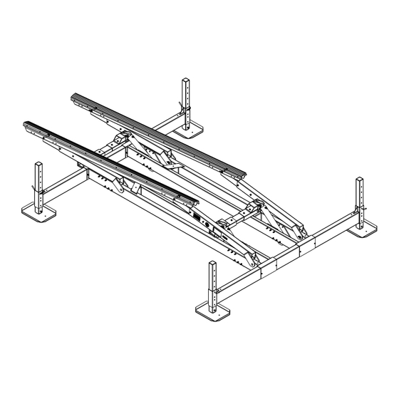
7.3. 4122214 HYDRAULIC CYLINDER ASSEMBLY REF # PART # DESCRIPTION 6041071 HYDRAULIC CYLINDER 3 X 15-7/8 4107955 HOSE ASSEMBLY 4’ W/STAINLESS FTG’S 4107958 HOSE ASSEMBLY 4-1/2’ W/STAINLESS FTG’S 4107964 HOSE ASSEMBLY 20’ W/STAINLESS FTG’S 5694102 1/4 TEE -STAINLESS 6041364 1/4 FEMALE COUPLING (SCREW TO CONNECT) 6041365 1/4 MALE COUPLING (SCREW TO CONNECT) 5694101... - Page 25 Figure 7-2: Complete HL Hydraulic Lift Assembly...
-
Page 26: Limited Product Warranty
Marine Products RGC Marine products, hereafter referred to as the “Manufacturer”, extend this limited warranty to the original purchaser of this product. The original purchaser, hereinafter referred to as the “Buyer”, is defined as the first legal owner of this product other than an authorized distributor or dealer who has bought the product from the Manufacturer for resale to the public. - Page 27 F. NO EXTENSION OF STATUTE OF LIMITATIONS ANY REPAIRS PERFORMED UNDER EITHER OF THESE WARRANTIES SHALL NOT IN ANY WAY EXTEND THE ONE-YEAR AND FIFTEEN-YEAR STATUTES OF LIMITATIONS CONTAINED IN THIS LIMITED WARRANTY. G. PROCEDURE FOR WARRANTY PERFORMANCE If the product fails to perform to the Manufacturer’s specifications, the Buyer must contact the dealer from whom the product was purchased.
-
Page 28: Commercial Product Provisions
N. NO AUTHORITY TO ALTER WARRANTY No agent, representative, distributor or dealer has any authority to alter the terms of this warranty in any way. O. SPECIFIC LEGAL RIGHTS This warranty gives you specific legal rights and you may also have other rights, which vary, from State to State. COMMERCIAL PRODUCT PROVISIONS II. - Page 29 THESE EXPRESS WARRANTIES ARE IN LIEU OF AND EXCLUDE ANY AND ALL OTHER WARRANTIES, EXPRESS OR IMPLIED, INCLUDING, BUT NOT LIMITED TO, THE IMPLIED WARRANTIES OR MERCHANTABILITY AND FITNESS FOR A PARTICULAR PURPOSE. H. PROCEDURE FOR WARRANTY PERFORMANCE If the product fails to perform to the Manufacturer’s specifications, the Buyer must contact the dealer from whom the product was purchased.
Need help?
Do you have a question about the HLF8k and is the answer not in the manual?
Questions and answers