
Related Manuals for RGC VL16092


Summary of Contents for RGC VL16092
- Page 1 VL16092 VERTICAL LIFT INSTRUCTIONS REIMANN & GEORGER CORPORATION MARINE PRODUCTS BUFFALO, NY P/N 6112069 11/16/99...
- Page 2 PRE-LIFTING CHECKLIST The lift and related equipment must be thoroughly inspected prior to each use. Only those who have read and understood this entire manual and related equipment manuals are qualified to do this inspection. This checklist is to be used as a guideline in conjunction with the maintenance and inspection procedures outlined in this manual.
- Page 3 PRE-LIFTING CHECKLIST (CONTINUED) Insure the plastic caps are installed onto the tops of the vertical legs and the ends of the upper short horizontal tubes. INSPECTOR: _____________________________________ DATE: ______________...
-
Page 4: Table Of Contents
#3616020 VL 16092 Bundle 1 of 2..................23 7.1.2 #3616021 VL 16092 Bundle 2 of 2..................23 VL Extension Legs ........................ 23 #3679355 VL Bunk Carton of Parts..................23 #3603778 VL Bunk Bundle ....................24 RGC MARINE PRODUCTS 11/16/99 PHONE: (716) 895-1156... - Page 5 Platform Assembly–Top View ....................10 Frame Squaring Assembly / Table ..................11 Lower Diagonal Brace Assembly..................12 Cable Reeving & Adjustment....................13 VL Handwheel / Winch Mounting & Reeving..............14 Wire Rope Components ......................19 RGC MARINE PRODUCTS 11/16/99 PHONE: (716) 895-1156...
-
Page 6: Safety
WARNING: DO NOT OPERATE THIS LIFT WITHOUT STUDYING THIS ENTIRE MANUAL. FAILURE TO DO THIS CAN LEAD TO EQUIPMENT MISUSE WITH RESULTING DAMAGE AND/OR SERIOUS PERSONAL INJURY. CONTACT YOUR RGC® MARINE DEALER IF YOU HAVE ANY QUESTIONS. 1.2 SAFETY DEFINITIONS A safety message alerts you to potential hazards that could hurt you or others or cause property damage. -
Page 7: Installation Safety
WARNING: DO NOT STAND OR WALK ON THE PLATFORM WHILE IT IS IN ANY RAISED POSITION. THIS CAN CAUSE SERIOUS PERSONAL INJURY. 6. Do not allow anyone to swim or play under, near or on the lift at any time. 1.5 INSTALLATION SAFETY 1. -
Page 8: Safety When Raising The Boat
11. Contact your dealer if the winch mechanism fails to perform as described in the Operation chapter of this manual. 12. Never tamper with the winch mechanism. This can cause equipment damage. 13. Do not operate the lift under the influence of drugs, alcohol, or medication. 14. - Page 9 WARNING: NEVER ALLOW ANYBODY TO WORK IN OR ON THE BOAT WHEN IT IS SUSPENDED ABOVE THE WATER ON THE LIFT. 3. Immediately replace any components found to be defective as described in Chapter 5—Inspection and Maintenance.
-
Page 10: Specifications
2 SPECIFICATIONS 2.1 TECHNICAL DATA MODEL VL16092 Weight Capacity 1600 lbs. Maximum Beam 92” Lifting Height 66” Overall Width (Including Feet) 100” Overall Length (Including Feet) 108” 12’ Full Length Bunks Std. S.S. Aircraft Cable Std. Polymer Sheaves Std. K-2550 Winch Std. -
Page 11: Optional Equipment
2.3 OPTIONAL EQUIPMENT The following options are available which enable you to customize your lift for your particular operation. Installation instructions are provided as part of each option kit. 1. Acrylic Canopy— Boats tucked neatly under the heavy duty canopy are protected from the elements, reducing the need for boat coverings. -
Page 12: Installation And Setup
3 INSTALLATION AND SETUP 3.1 PRE-INSTALLATION CHECKS 1. Do not assemble the lift if any part shows any sign of damage. 2. Do not weld or otherwise modify the lift. Such alterations may weaken the structural integrity of the lift and void the warranty. -
Page 13: Vertical Leg Assembly
The lift may be placed on either side of your dock as shown in Figure 3-2. The winch is mounted onto vertical leg A. Figure 3-2 Lift / Dock Placement Options Place one bag of hardware at each corner. CAUTION: INSERT ALL BOLTS FROM THE INSIDE OF THE LIFT TO PREVENT DAMAGE TO YOUR BOAT. -
Page 14: Frame Side Assembly
3.4 FRAME SIDE ASSEMBLY 1. Refer to Figure 3-4. Fasten a pair of short horizontal tubes between vertical legs A and D with hardware shown. DO NOT TIGHTEN. 2. Repeat the procedure for vertical legs B and C. 3. Lay the assembled sides down on the ground with the foot plates facing one another and aligned, about 9 feet apart. 4. -
Page 15: Mounting The Platform To The Frame
Figure 3-5 Platform Assembly – Top View 3.6 MOUNTING THE PLATFORM TO THE FRAME 1. Insure all platform fastenings are tight before mounting onto the frame. 2. Lift one of the frame sides and position it along a spreader tube side of the platform. 3. -
Page 16: Mounting The Lower Diagonal Braces
7. Install the eight (8) plastic caps provided onto the tops of the four vertical legs and the ends of the upper short horizontal tubes. MODEL “X” DIM “Y” DIM VL16092 92 IN. 90 IN. Note: Values shown are approx. Figure 3-6 Frame Squaring Assembly / Table 3.7 MOUNTING THE LOWER DIAGONAL BRACES... -
Page 17: Platform Reeving And Adjustment
Figure 3-7 Lower Diagonal Brace Assembly 3.8 PLATFORM REEVING AND ADJUSTMENT 1. Position the platform near the bottom end of its lifting range. Insure the platform is level. 2. Refer to Figure 3-8. The load and spreader tubes are already reeved. Fasten the cable end loops to the bracket provided at the bottom of each of the four vertical legs. -
Page 18: Winch/Handwheel Mounting
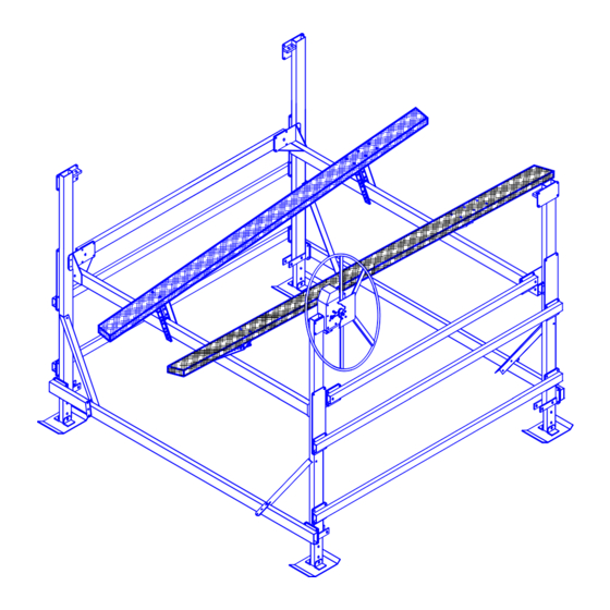
Figure 3-8 Cable Reeving & Adjustment 6. If the boat is not lifting level because the stern is lifting higher or lower than the bow, the spreader tube cables are not tight enough. Repeat the first two substeps under Step 3 above. 3.9 WINCH / HANDWHEEL MOUNTING 1. -
Page 19: Reeving The Winch
CAUTION: DO NOT USE THE SPINNER KNOB FOR LIFTING THE BOAT. THIS CAN CAUSE EQUIPMENT DAMAGE. Figure 3-9 VL Handwheel / Winch Mounting and Reeving 3.10 REEVING THE WINCH 1. Refer to Figure 3-8. Attach the A-B load tube cable stud to vertical leg “B” . 2. -
Page 20: Moving Lift To Operating Position
WARNING: WHEN REEVING THE WINCH, CLOCKWISE ROTATION OF THE HANDWHEEL MUST RAISE, NOT LOWER, THE PLATFORM. IF CLOCKWISE ROTATION OF THE HANDWHEEL LOWERS THE PLATFORM, YOU HAVE REEVED THE WINCH INCORRECTLY. AN UNCONTROLLED FREEWHEELING CAN BE TRIGGERED WITH THE WEIGHT OF A BOAT. FREEWHEELING CAN CAUSE EQUIPMENT OR BOAT DAMAGE. -
Page 21: Operation
4 OPERATION 4.1 BEFORE OPERATING THE LIFT 1. Read and know the instructions and insure that everyone understands the proper operating procedure. 2. When using a power drive, understand the use of all controls and connections provided with it. 3. Follow the Pre-Lifting Checklist before operating. 4. -
Page 22: Raising And Lowering The Platform
3. Lower the empty platform to repeat steps 1 and 2 with your boat on the lift. The handwheel or power drive must turn counter-clockwise when lowering the platform. This counter-clockwise rotation allows the self-activating brake mechanism to stop the platform lowering as soon as the operator stops turning the handwheel. Make sure this brake mechanism is operative. -
Page 23: Inspection And Maintenance
5 INSPECTION AND MAINTENANCE 5.1 GENERAL MAINTENANCE RULES 1. Do not allow persons other than authorized service personnel to repair this equipment. 2. If slings are used, inspect them for deterioration. Replace them immediately if they are worn. 3. Do not weld or otherwise modify the lift. Such alterations may weaken the structural integrity of the lift and invalidate your warranty. -
Page 24: Annual Inspection
Figure 5-1 Wire Rope Components 5. Heat damage: Evidence of any heat damage caused by a torch or by contact with electrical wires. 6. Reduction of more than 1/64 inch from a nominal 5/16-inch or less diameter cable. Reduction of more than 1/32 inch from a nominal 3/8-inch to 1/2-inch diameter cable. -
Page 25: Storage Procedure
6. Remove acorn nut on handwheel and turn counterclockwise to remove wheel to clearly expose the input shaft threads. 7. Grease threads; avoid contaminating fibrous brake disk. 8. Thread wheel back on until brake pawl begins clicking. Reinstall and tighten acorn nut. WARNING: AFTER EVERY WINCH MAINTENANCE, TEST THE WINCH MECHANISM AS DESCRIBED IN CHAPTER 4 BEFORE LETTING ANYONE USE THE LIFT. -
Page 26: Troubleshooting
6 TROUBLESHOOTING The following chart is intended to assist with troubleshooting your vertical lift. While not all inclusive, the chart outlines the most common causes of a problem and the recommended course of action. SYMPTOM CAUSE AND CORRECTIVE ACTION Winch resists platform raising. Winch has been reeved incorrectly—winch must turn clockwise to raise platform. - Page 27 Lowering operation triggers a “freewheeling” of Winch has been reeved incorrectly—winch must turn the handwheel. counterclockwise to lower the platform. See Section 3.10. Unauthorized brake pawl release has occurred—do not try to correct this yourself. Contact your authorized dealer immediately. WARNING: NEVER RELEASE THE BRAKE PAWL OF THE WINCH.
-
Page 28: Parts Lists
7 PARTS LISTS Each item number or letter in the following parts lists can be matched with the item number or letter referred to in both the text and illustrations of Sections 3.1 through 3.9 of Chapter 3, Installation and Setup. 7.1 #3616000 VL 16092 BOAT LIFT BUNDLES 7.1.1 #3616020 VL 16092 Bundle 1 of 2... -
Page 29: 3616033 Vl 16092 Carton Of Parts
7.5 #3616033 VL 16092 CARTON OF PARTS REF # PART # DESCRIPTION 3638145 WINCH K2550 W / HOLES 3703142 WINCH CABLE CLAMP KIT 3616087 VL 16092 FULTON WINCH BAG OF BOLTS consisting of: 3603835 VL 2” WINCH BOLT PLATE 6408069 CAP THREAD 11/32 X 1/2”... -
Page 30: Limited Warranty
REIMANN & GEORGER CORPORATION MARINE PRODUCTS RGC Marine products, hereafter referred to as the “Manufacturer”, extends this limited warranty to the original purchaser of this product. The original purchaser, hereinafter referred to as the “Buyer”, is defined as the first legal owner of this product other than an authorized distributor or dealer who has bought the product from the Manufacturer for resale to the public. - Page 31 E. NO LIABILITY IN EXCESS OF PURCHASE PRICE IN NO EVENT SHALL THE MANUFACTURER’S OBLIGATIONS UNDER THIS LIMITED WARRANTY EXCEED THE PURCHASE PRICE OF THE PRODUCT. F. NO EXTENSION OF STATUTE OF LIMITATIONS ANY REPAIRS PERFORMED UNDER EITHER OF THESE WARRANTIES SHALL NOT IN ANY WAY EXTEND THE TWO-YEAR AND FIFTEEN-YEAR STATUTES OF LIMITATIONS CONTAINED IN THIS LIMITED WARRANTY.
- Page 32 4. Damage under conditions caused by fire or accident, by abuse or negligence, by improper installation, by misuse, by incorrect operation, by “normal wear and tear”, by improper adjustment or alteration, by alterations not done by the Manufacturer, or by failure of product parts from such alterations. 5.
- Page 33 COMMERCIAL PRODUCT PROVISIONS II. ARTICLE II—COMMERCIAL PRODUCT PROVISIONS: THE FOLLOWING PROVISIONS SHALL BE APPLICABLE ONLY IF THIS PRODUCT IS BEING PURCHASED SOLELY FOR COMMERCIAL OR INDUSTRIAL USE. IF THIS PRODUCT IS BEING PURCHASED FOR PERSONAL, FAMILY OR HOUSEHOLD PURPOSES, THE PROVISIONS CONTAINED IN THIS ARTICLE II SHALL NOT BE APPLICABLE AND THE PROVISIONS CONTAINED IN ARTICLE I ABOVE SHALL APPLY.
- Page 34 H. PROCEDURE FOR WARRANTY PERFORMANCE If the product fails to perform to the Manufacturer’s specifications, the Buyer must contact the dealer from whom the product was purchased. The Buyer must provide the dealer with the applicable model and serial numbers, the date of purchase, and the nature of the problem.
Need help?
Do you have a question about the VL16092 and is the answer not in the manual?
Questions and answers