
Related Manuals for RGC HL7000


Summary of Contents for RGC HL7000
- Page 1 HL7000/HL7000XL HYDRAULIC BOAT LIFT INSTRUCTIONS REIMANN & GEORGER CORPORATION MARINE PRODUCTS BUFFALO, NY P/N 6114162 02/10/17...
-
Page 3: Table Of Contents
HL70120 Common Bundle #2 ....................... 22 HL70112 Bundle #2 ........................22 HL Extension Legs ........................22 HL Aluminum Bunk Bundle ......................22 7.10 HL7K Hydraulic Cylinders & Fittings ................... 22 7.11 HL7K Hardware Carton of Parts ....................22 RGC MARINE PRODUCTS PHONE: (716) 895-1156... - Page 4 Main Frame, Cylinder Support Assembly ..................7 Lift Arm Assembly ......................... 8 Cylinder, Main Frame, & Leg Assembly ..................10 Bunk Assembly ..........................11 Hydraulic Cylinder and Hose Assembly ..................23 Complete Hydraulic Lift Assembly ....................24 RGC MARINE PRODUCTS PHONE: (716) 895-1156...
-
Page 5: Safety
DO NOT OPERATE THIS LIFT WITHOUT STUDYING THIS ENTIRE MANUAL. FAILURE TO DO THIS CAN LEAD TO EQUIPMENT MISUSE WITH RESULTING SERIOUS PERSONAL INJURY AND/OR DAMAGE. CONTACT YOUR RGC MARINE DEALER IF YOU HAVE ANY QUESTIONS. 1.2 SAFETY DEFINITIONS A safety message alerts you to potential hazards that could hurt you or others or cause property damage. -
Page 6: Installation Safety
12. Never use the lift to hang or store any auxiliary equipment such as boating hardware. 13. Never operate the lift during an electrical storm. 1.5 INSTALLATION SAFETY Do not weld or otherwise modify the lift. Such alterations may weaken the structural integrity of the lift and void the warranty. -
Page 7: Specifications
2 SPECIFICATIONS 2.1 TECHNICAL DATA Model HL70120 HL70120XL Weight Capacity 7000 lbs. 7000 lbs. Maximum Beam 120” 120” Lifting Height 48” 60” Min. Water Depth 29” 30” Overall Width (Including Feet) 137” 137” Overall Length (Including Feet) 198” 209” 12’ Full Length Bunks Std. -
Page 8: Optional Equipment
2.3 OPTIONAL EQUIPMENT The following options are available which enable you to customize your lift for your particular operation. Installation instructions are provided as part of each option kit. Canopies— Boats tucked neatly under the heavy duty canopy are protected from the elements, reducing the need for boat coverings. -
Page 9: Installation And Setup
3 INSTALLATION AND SETUP 3.1 PRE-INSTALLATION CHECKS Do not assemble the lift if any part shows any sign of damage. Do not weld or otherwise modify the lift. Such alterations may weaken the structural integrity of the lift and void the warranty. -
Page 10: Leg Pocket Assembly
3.3 LEG POCKET ASSEMBLY Refer to Figure 3-1. Fasten foot plate (1) to extension leg (2) using hardware (C) and (D). Insert foot plate and extension leg assembly into leg assembly (3). Insert leg pin and clip (A) to secure. Install the four plastic cap plugs (Z) onto ends of the extension legs. -
Page 11: Cylinder Support Assembly
3.4 CYLINDER SUPPORT INSTALLATION Refer to Figure 3-2. Install the left (6) and right (7) cylinder support plates onto the right hand main frame (5). Install cylinder support plates so that the welded bosses on the support plates are facing each other. Secure the cylinder support plates with hardware E, F, G, H, &... -
Page 12: Lifting Arm Installation
3.5 LIFT ARM INSTALLATION Refer to Figure 3-3. Install rear lift arm (8) to the main frame. Before inserting clevis pin (B), install nylon washer (J) between the main frame and the lift arm pivot plates. Insert clevis pin (B) through the lift arm end plates and hole in the lift frame. -
Page 13: Hose/Cylinder Assembly Installation
3.6 HOSE / CYLINDER ASSEMBLY INSTALLATION Refer to Figure 3-4. Install the hydraulic cylinders (11) onto the main frame. Place the cylinders in position so that the hydraulic fittings are facing upward. Place the cylinders in position and insert pin (L) through only one cylinder support plate. -
Page 14: Main Frame And Leg Assembly
Figure 3-4. Cylinder, Main Frame and Leg Assembly (Figure shown without hoses for clarity) 3.7 MAIN FRAME AND LEG ASSEMBLY Refer to Figure 3-4. Install left side main frame (4) and right side main frame (5) onto each leg assembly. Center the main frames onto the leg assembly as close to center as possible. -
Page 15: Making Power Connections
Repeat steps 1 thru 3 to assemble other bunk. Figure 3-5. Bunk Assembly 3.9 MAKING POWER CONNECTIONS Before making any hydraulic connections, inspect all hydraulic lines, fittings and hoses for leaks and risks of rupture as follows: Inspect each hydraulic line, fitting, and hose for breaks, cracks, worn spots, bulges, chemical attack, kinks or any other damage. -
Page 16: Operating Position
fitting. This will release a small amount of fluid, which is acceptable. Once the pressure has been released, you should be able to connect both hoses. WARNING: ENSURE HYDRAULIC HOSES ARE PROPERLY CONNECTED AND IN GOOD CONDITION. Ensure that the hydraulic fluid supply is adequate. Attach the red battery lead to the positive battery terminal, and the black lead to the negative terminal. -
Page 17: Operation
4 OPERATION 4.1 BEFORE OPERATING THE LIFT Review and follow all the safety precautions given in Chapter 1. Do not use the lift if it shows any signs of damage. Ensure that all bolts and nuts are fastened securely prior to operation. Ensure that the frame is square and that the lift sits level. -
Page 18: Testing Lift Operation With Remotes
4.3 TESTING LIFT WITH REMOTES To unlock the remotes, press the two blue buttons simultaneously, this will unlock the unit. Press the ‘UP’ button to raise the lift platform. Press the ‘DOWN’ button to lower the lift platform. To lock the remote, press the two blue buttons simultaneously. 4.4 RAISING AND LOWERING THE BOAT Position the boat so that the boat’s center of gravity is between forward and rear support legs. -
Page 19: Inspection And Maintenance
5 INSPECTION AND MAINTENANCE 5.1 GENERAL MAINTENANCE RULES Do not allow persons other than authorized service personnel to repair this equipment. Completely lower the platform before performing any type of maintenance or repair. WARNING: NEVER ALLOW ANYBODY TO WORK IN OR ON THE BOAT WHEN IT IS SUSPENDED ABOVE THE WATER ON THE LIFT. -
Page 20: Remote Control Information
Proper function of the RC system is dependent upon several factors that are not controllable by the manufacturer. RGC is not responsible for the following: Improper installation, low battery, natural occurrences, use other than intended, location of... -
Page 21: Annual Inspection
5.4 ANNUAL INSPECTION At least once a year, the lift must be thoroughly inspected using the following procedure. WARNING: DO NOT ALLOW ANYBODY TO USE THE LIFT UNTIL THIS MAINTENANCE IS COMPLETED. Tighten all bolts. Clean cylinder rods. Check that all the pivot pins are lubricated properly. Check frame thoroughly for defects. -
Page 22: Hydraulic System Flush
It is recommended that as part of an annual maintenance program, the hydraulic system be drained and fresh Vegetable Grade hydraulic oil installed. RGC recommends CITGO Aqua Marine Hydraulic 46 (or equivalent biodegradable oil) be used. Lower the platform until the cylinders are fully retracted. -
Page 23: Troubleshooting
6 TROUBLESHOOTING The following chart is intended to assist with troubleshooting your hydraulic lift. While not all inclusive, the chart outlines the most common causes of a problem and the recommended course of action. CAUTION: IF THE PROBLEM WITH THE POWER SUPPLY IS NOT CERTAIN, ALWAYS FOLLOW THE MANUFACTURER’S WARRANTY POLICY BEFORE ANY OTHER REPAIR OR MAINTENANCE IS ATTEMPTED. - Page 24 Remote control range is limited. Check battery in key chain transmitter. If the range is only limited while in your boat, try holding the transmitter over your head. Proximity to cell phone towers, power lines, and other electromagnetic interference can also reduce remote control range.
-
Page 25: Parts Lists
7 PARTS LISTS Each reference number or letter in the following parts lists can be matched with the reference number or letter referred to in both the text and illustrations of Chapter 3, Installation and Setup. WARNING: FAILURE TO APPLY A SUITABLE LUBRICANT TO THE MATING SURFACES OF STAINLESS STEEL THREADED FASTENERS MAY CAUSE GALLING AND/OR SEIZING OF ASSEMBLY. -
Page 26: Hl70120 Common Bundle #2
7.7 4107121 HL70112 BUNDLE #2 (112” WIDE LIFT) REF # PART # DESCRIPTION 4107595 HL6-7K LEG ASSEMBLY 112” 4107564 HL7K MAIN FRAME ASSEMBLY LH 4107567 HL7K MAIN FRAME ASSEMBLY RH 7.8 HL EXTENSION LEGS REF # PART # DESCRIPTION as ordered HL EXTENSION LEGS 3’... -
Page 27: Hydraulic Cylinder And Hose Assembly
4107306 HL7K CLEVIS PIN BAG consisting of: 4107934 2-1/4” OD X .91” ID X 1/16” THICK NYLON LIFTARM WASHER 5894109 HL CLEVIS PIN ¾” X 5” HEADED 4107919 7/8 X 7-1/16 CYLINDER BOTTOM CLEVIS PIN 4107913 7/8 X 4-1/8 CYLINDER TOP CLEVIS PIN 4107949 2”... -
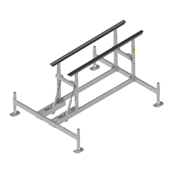
Page 28: Complete Hydraulic Lift Assembly
Figure 7-2 Complete Hydraulic Lift Assembly... - Page 29 Marine Products RGC Marine products, hereafter referred to as the “Manufacturer”, extend this limited warranty to the original purchaser of this product. The original purchaser, hereinafter referred to as the “Buyer”, is defined as the first legal owner of this product other than an authorized distributor or dealer who has bought the product from the Manufacturer for resale to the public.
- Page 30 F. NO EXTENSION OF STATUTE OF LIMITATIONS ANY REPAIRS PERFORMED UNDER EITHER OF THESE WARRANTIES SHALL NOT IN ANY WAY EXTEND THE ONE-YEAR AND FIFTEEN-YEAR STATUTES OF LIMITATIONS CONTAINED IN THIS LIMITED WARRANTY. G. PROCEDURE FOR WARRANTY PERFORMANCE If the product fails to perform to the Manufacturer’s specifications, the Buyer must contact the dealer from whom the product was purchased.
- Page 31 M. RIGHT TO MODIFY PRODUCT The Manufacturer has the right to modify this product at any time without incurring any obligation to make the same or similar modifications on products previously purchased. N. NO AUTHORITY TO ALTER WARRANTY No agent, representative, distributor or dealer has any authority to alter the terms of this warranty in any way. O.
- Page 32 COMMERCIAL PRODUCT PROVISIONS II. ARTICLE II—COMMERCIAL PRODUCT PROVISIONS: THE FOLLOWING PROVISIONS SHALL BE APPLICABLE ONLY IF THIS PRODUCT IS BEING PURCHASED SOLELY FOR COMMERCIAL OR INDUSTRIAL USE. IF THIS PRODUCT IS BEING PURCHASED FOR PERSONAL, FAMILY OR HOUSEHOLD PURPOSES, THE PROVISIONS CONTAINED IN THIS ARTICLE II SHALL NOT BE APPLICABLE AND THE PROVISIONS CONTAINED IN ARTICLE I ABOVE SHALL APPLY.
- Page 33 I. PREAPPROVAL OF LABOR COSTS All labor costs related to a dealer’s performance of the warranty obligations under this limited warranty must be pre-approved by Reimann & Georger Corp. Marine Products. J. EXCLUSIONS FROM WARRANTY. THIS LIMITED WARRANTY DOES NOT COVER ANY OF THE FOLLOWING: Equipment which has been abused, damaged, used beyond rated capacity, or which is damaged or has defects caused by repairs or service completed by persons other than authorized service personnel.
Need help?
Do you have a question about the HL7000 and is the answer not in the manual?
Questions and answers