
Related Manuals for RGC VL4000


Summary of Contents for RGC VL4000
- Page 1 VL4000 VERTICAL LIFT INSTRUCTIONS REIMANN & GEORGER CORPORATION MARINE PRODUCTS BUFFALO, NY P/N 6112070 3/1/01...
- Page 2 PRE-LIFTING CHECKLIST The lift and related equipment must be thoroughly inspected prior to each use. Only those who have read and understood this entire manual and related equipment manuals are qualified to do this inspection. This checklist is to be used as a guideline in conjunction with the maintenance and inspection procedures outlined in this manual.
-
Page 3: Table Of Contents
Wire Rope Inspection Procedure....................19 Annual Inspection..........................20 Annual Winch Maintenance ......................20 Storage Procedure..........................21 TROUBLESHOOTING......................23 PARTS LISTS..........................25 #3641080 VL 40108 Bundles......................25 7.1.1 #3640120 VL 40108 Bundle 1 of 2....................25 7.1.2 #3640121 VL 40108 Bundle 2 of 2....................25 RGC MARINE PRODUCTS PHONE: (716) 895-1156... - Page 4 Frame Side Assembly........................9 Platform Assembly—Top View ....................10 Frame Squaring Assembly/Table ....................11 Lower Diagonal Brace Assembly....................12 Cable Reeving & Adjustment......................13 VL Handwheel Mounting......................14 3-10 Winch Cable Reeving........................15 Wire Rope Components ........................20 Exploded Assembly Drawings ..................... Chapter 7 RGC MARINE PRODUCTS PHONE: (716) 895-1156...
-
Page 5: Safety
WARNING: DO NOT OPERATE THIS LIFT WITHOUT STUDYING THIS ENTIRE MANUAL. FAILURE TO DO THIS CAN LEAD TO EQUIPMENT MISUSE WITH RESULTING DAMAGE AND/OR SERIOUS PERSONAL INJURY. CONTACT YOUR RGC® MARINE DEALER IF YOU HAVE ANY QUESTIONS. 1.2 SAFETY DEFINITIONS A safety message alerts you to potential hazards that could hurt you or others or cause property damage. -
Page 6: Installation Safety
WARNING: DO NOT STAND OR WALK ON THE PLATFORM WHILE IT IS IN ANY RAISED POSITION. THIS CAN CAUSE SERIOUS PERSONAL INJURY. 6. Do not allow anyone to swim or play under, near or on the lift at any time. 1.5 INSTALLATION SAFETY 1. -
Page 7: Safety When Raising The Boat
12. Never tamper with the winch mechanism. This can cause equipment damage. 13. Do not operate the lift under the influence of drugs, alcohol, or medication. 14. Never use the lift to hang or store any auxiliary equipment such as boating hardware. 1.6.2 Safety When Raising the Boat 1. -
Page 8: Specifications
2 SPECIFICATIONS 2.1 TECHNICAL DATA MODEL VL40108 VL40116 Weight Capacity 4000 lbs. 4000 lbs. Maximum Beam 108” 116” Lifting Height 66” 66” Std. Adjustable Legs 4 at 24” 4 at 24” Overall Width (Including Feet) 116” 124” Overall Length (Including Feet) 116”... - Page 9 2. Direct Drive AC 110V—For added ease of operation, a heavy duty AC motorized direct drive mounts in place of the standard handwheel and lifts your boat out of the water. Exclusive right angle design minimizes intrusion of dock space. A radio control option is available. 3.
-
Page 10: Installation And Setup
3 INSTALLATION AND SETUP 3.1 PRE-INSTALLATION CHECKS 1. Do not assemble the lift if any part shows any sign of damage. 2. Do not weld or otherwise modify the lift. Such alterations may weaken the structural integrity of the lift and void the warranty. -
Page 11: Vertical Leg Assembly
The lift may be placed on either side of your dock as shown in Figure 3-2. The winch is mounted onto vertical leg A. Figure 3-2 Lift / Dock Placement Options Place one bag of hardware at each corner. CAUTION: INSERT ALL BOLTS FROM THE INSIDE OF THE LIFT TO PREVENT DAMAGE TO YOUR BOAT. -
Page 12: Frame Side Assembly
3.4 FRAME SIDE ASSEMBLY 1. Refer to Figure 3-4. Fasten a pair of short horizontal tubes between vertical legs A and D with hardware shown. DO NOT TIGHTEN. 2. Repeat the procedure for vertical legs B and C. 3. Lay the assembled sides down on the ground with the foot plates facing one another and aligned, about 9 feet apart. 4. -
Page 13: Mounting The Platform To The Frame
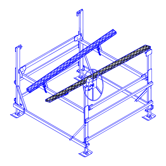
Figure 3-5 Platform Assembly – Top View 3.6 MOUNTING THE PLATFORM TO THE FRAME 1. Insure all platform fastenings are tight before mounting onto the frame. 2. Lift one of the frame sides and position it along a spreader tube side of the platform. 3. -
Page 14: Mounting The Lower Diagonal Braces
MODEL “X” DIM “Y” DIM VL40108 108 IN. 98 IN. VL40116 116 IN. 98 IN. Note: Values shown are approx. Figure 3-6 Frame Squaring Assembly / Table 3.7 MOUNTING THE LOWER DIAGONAL BRACES 1. Position a lower diagonal brace on the inside of vertical leg “B” as shown in Figure 3-7. Loosely fasten with hardware shown. -
Page 15: Platform Reeving And Adjustment
Figure 3-7 Lower Diagonal Brace Assembly 3.8 PLATFORM REEVING AND ADJUSTMENT 1. Position the platform near the bottom end of its lifting range. Insure the platform is level. 2. Refer to Figure 3-8. The load and spreader tubes are already reeved. Fasten the cable end loops to the bracket provided at the bottom of each of the four vertical legs. -
Page 16: Winch/Handwheel Mounting
6. If the boat is not lifting level because the stern is lifting higher or lower than the bow, the spreader tube cables are not tight enough. Repeat the first two substeps under Step 3 above. Figure 3-8 Cable Reeving & Adjustment 3.9 WINCH/HANDWHEEL MOUNTING 1. -
Page 17: Reeving The Winch
Figure 3-9 VL Handwheel Mounting 3.10 REEVING THE WINCH 1. Refer to Figure 3-10. Remove the top and bottom guards from the winch housing by removing the (4) ¼ -20 pan head screws. 2. Position the winch drum so that the set screw faces at a 90° angle or perpendicular to, the vertical leg “A”. 3. -
Page 18: Moving Lift To Operating Position
6. When the winch reeving is done, the guards must be reinstalled. Do NOT operate the winch without the guards installed. 7. Refer to Figure 3-8. Tighten down the nut to fasten the A-B load tube cable stud to leg B. Add and tighten a jam nut to the cable nut to lock the position. - Page 19 CAUTION: FRAME MUST BE SQUARE TO PREVENT DAMAGE AND/OR IMPROPER FITTING OF CANOPY FABRIC IF SO EQUIPPED. 3. Verify frame is square by measuring the diagonal distance from the outside of frame corner to opposite corner. Repeat for alternate corners. The difference between the two measurements shall not exceed 1/4 of an inch . Frame Diagonal Measurement Diagram (Measure to Outside Corners)
-
Page 20: Operation
4 OPERATION 4.1 BEFORE OPERATING THE LIFT 1. Read and know the instructions and insure that everyone understands the proper operating procedure. 2. When using a power drive, understand the use of all controls and connections provided with it. 3. Follow the Pre-Lifting Checklist before operating. 4. -
Page 21: Raising And Lowering The Platform
4. Contact your authorized dealer if the winch mechanism fails to perform as described in this section. Do NOT tamper with the winch mechanism. 4.3 RAISING AND LOWERING THE PLATFORM 1. Raise the platform by turning the handwheel clockwise. The self-activating brake mechanism will hold the platform at any desired height. -
Page 22: Inspection And Maintenance
5 INSPECTION AND MAINTENANCE 5.1 GENERAL MAINTENANCE RULES 1. Do not allow persons other than authorized service personnel to repair this equipment. 2. If slings are used, inspect them for deterioration. Replace them immediately if they are worn. 3. Do not weld or otherwise modify the lift. Such alterations may weaken the structural integrity of the lift and invalidate your warranty. -
Page 23: Annual Inspection
Figure 5-1. Wire Rope Components 5. Heat damage: Evidence of any heat damage caused by a torch or by contact with electrical wires. 6. Reduction of more than 1/64 inch from a nominal 5/16-inch or less diameter cable. Reduction of more than 1/32 inch from a nominal 3/8-inch to 1/2-inch diameter cable. -
Page 24: Storage Procedure
7. Grease threads, avoid contaminating fibrous brake disk. 8. Thread wheel back on until brake pawl begins clicking. Reinstall and tighten acorn nut. WARNING: AFTER EVERY WINCH MAINTENANCE, TEST THE WINCH MECHANISM AS DESCRIBED IN CHAPTER 4 BEFORE LETTING ANYONE USE THE LIFT. 5.5 STORAGE PROCEDURE 1. -
Page 25: Troubleshooting
6 TROUBLESHOOTING The following chart is intended to assist with troubleshooting your vertical lift. While not all inclusive, the chart outlines the most common causes of a problem and the recommended course of action. SYMPTOM CAUSE AND CORRECTIVE ACTION Winch resists platform raising. Winch has been reeved incorrectly—winch must turn clockwise to raise platform. - Page 26 Boat shifts position when operating the lift. Boat is not properly secured on the lift—failure to properly secure boat can cause equipment damage and/or serious personal injury. Lowering operation triggers a “freewheeling” of Winch has been reeved incorrectly—winch must turn the handwheel.
-
Page 27: Parts Lists
7 PARTS LISTS Each reference number or letter in the parts lists of Sections 7.1 through 7.6 can be matched with the reference number or letter referred to in both the text and illustrations of Chapter 3, Installation and Setup. 7.1 #3641080 VL 40108 BUNDLES 7.1.1 #3640120 VL 40108 Bundle 1 of 2... -
Page 28: Vl Bunks 1.6-4K
7.4 VL BUNKS 1.6–4K REF # PART # DESCRIPTION 3603778 VL WOOD BUNDLE 1.6-4K 3679355 VL SS CARTON 1.6–4K 3603936 VL/AR CRADLE BRACKET–STD 3603937 VL CRADLE BRACKET FLAT 15-7/8 3603938 VL CRADLE BRACKET ANG 15-7/8 3605977 VL BUNK SS BAG OF BOLTS 1.6–4K 7.5 VL 40108 AND VL 40116 COMMON HARDWARE REF # PART #... - Page 29 Marine Products RGC Marine products, hereafter referred to as the “Manufacturer”, extends this limited warranty to the original purchaser of this product. The original purchaser, hereinafter referred to as the “Buyer”, is defined as the first legal owner of this product other than an authorized distributor or dealer who has bought the product from the Manufacturer for resale to the public.
- Page 30 E. NO LIABILITY IN EXCESS OF PURCHASE PRICE IN NO EVENT SHALL THE MANUFACTURER’S OBLIGATIONS UNDER THIS LIMITED WARRANTY EXCEED THE PURCHASE PRICE OF THE PRODUCT. F. NO EXTENSION OF STATUTE OF LIMITATIONS ANY REPAIRS PERFORMED UNDER EITHER OF THESE WARRANTIES SHALL NOT IN ANY WAY EXTEND THE TWO-YEAR AND FIFTEEN-YEAR STATUTES OF LIMITATIONS CONTAINED IN THIS LIMITED WARRANTY.
- Page 31 5. Costs of repairing damage caused by poor or improper maintenance, costs of normally scheduled maintenance, or the cost of replacing any parts unless done as the result of a repair covered by your two-year limited warranty. 6. Costs of modifying the product in any way once delivered to the Buyer, even if such modifications were added as a production change on other products made after the Buyer’s product was built.
- Page 32 COMMERCIAL PRODUCT PROVISIONS II. ARTICLE II—COMMERCIAL PRODUCT PROVISIONS: THE FOLLOWING PROVISIONS SHALL BE APPLICABLE ONLY IF THIS PRODUCT IS BEING PURCHASED SOLELY FOR COMMERCIAL OR INDUSTRIAL USE. IF THIS PRODUCT IS BEING PURCHASED FOR PERSONAL, FAMILY OR HOUSEHOLD PURPOSES, THE PROVISIONS CONTAINED IN THIS ARTICLE II SHALL NOT BE APPLICABLE AND THE PROVISIONS CONTAINED IN ARTICLE I ABOVE SHALL APPLY.
- Page 33 I. PREAPPROVAL OF LABOR COSTS All labor costs related to a dealer’s performance of the warranty obligations under this limited warranty must be pre- approved by Reimann & Georger Corp. Marine Products. J. EXCLUSIONS FROM WARRANTY. THIS LIMITED WARRANTY DOES NOT COVER ANY OF THE FOLLOWING: 1.
Need help?
Do you have a question about the VL4000 and is the answer not in the manual?
Questions and answers