
Related Manuals for RGC HL20058


Summary of Contents for RGC HL20058
- Page 1 HL20058, HL20065 HYDRAULIC BOAT LIFT INSTRUCTIONS (Applies to P/N’s 4108800, 4108803, 4108806) REIMANN & GEORGER CORPORATION P/N 6115018 Marine Products Division 2/28/2023...
-
Page 2: Table Of Contents
Contents SAFETY ............................... 2 1.1. INTRODUCTION .............................. 2 1.2. SAFETY DEFINITIONS............................ 2 1.3. EQUIPMENT SAFETY LABELS ........................2 1.4. EQUIPMENT AND PERSONNEL SAFETY ....................2 1.5. INSTALLATION SAFETY ..........................3 1.6. OPERATING SAFETY ............................3 SPECIFICATIONS ............................4 2.1. NAMEPLATE AND SERIAL NUMBER TAG....................5 2.2. -
Page 3: Safety
WARNING: DO NOT OPERATE THIS LIFT WITHOUT STUDYING THIS ENTIRE MANUAL. FAILURE TO DO THIS CAN LEAD TO EQUIPMENT MISUSE WITH RESULTING SERIOUS PERSONAL INJURY AND/OR DAMAGE. CONTACT YOUR RGC MARINE DEALER IF YOU HAVE ANY QUESTIONS. 1.2. SAFETY DEFINITIONS A safety message alerts you to potential hazards that could hurt you or others or cause property damage. -
Page 4: Installation Safety
1.5. INSTALLATION SAFETY Do not weld or otherwise modify the lift. Such alterations may weaken the structural integrity of the lift and void the warranty. All lifting accessories such as pontoon brackets, pivoting bunks, and guide-ons, must be commercially manufactured, and be properly maintained and installed. -
Page 5: Specifications
SPECIFICATIONS Model HL20058-48 HL20065-48 HL20065-60 Part Number 4108803 4108806 4108800 Weight Capacity 2000 lb 2000 lb 2000 lb Maximum Beam 58” 65” 65” Overall Width (incl feet) 73 ½” 80 ½” 80 ½” Width at Bunks 26” 26” 26” Keel Clearance from Bunks 6”... -
Page 6: Nameplate And Serial Number Tag
2.1. NAMEPLATE AND SERIAL NUMBER TAG It is important to identify your lift completely and accurately whenever ordering spare parts or requesting assistance in service. There are two product nameplates for each lift; one nameplate located at the top of the Right-Hand Forward Lift Arm and another nameplate in the control box. -
Page 7: Installation And Setup
INSTALLATION AND SETUP 3.1. Pre-Installation Checks Do not assemble the lift if any part shows any sign of damage. Do not weld or otherwise modify the lift. Such alterations may weaken the structural integrity of the lift and void the warranty. -
Page 8: Leg & Main Frame Assembly
3.3. Leg & Main Frame Assembly At each corner, attach extension leg to foot plate (2) as shown. Install cap (27). Slide extension leg to required height in leg (3) and secure with leg pin (1). Ensure each leg sits level. For very shallow water applications: A 12”... -
Page 9: Liftarm Installation
3.4. Liftarm Installation Position rear liftarm (9) above the cylinder cross tube on the main frame in the orientation as shown. Secure to main frame with pin (19), stainless washer (25), and cotter pin (17). Position front liftarm (11) at the end of the main frame, in the orientation shown. Secure to main frame with pin (19), stainless washer (25), and cotter pin (17). -
Page 10: Cylinder Installation
3.5. Cylinder Installation Gently lower the bunks. Uncoil cylinder hoses and pass them under the rails of the main frame (10). Position the cylinder (8) with the fittings down to avoid contact between boat hull and cylinder fitting. Secure the large end of cylinder (8) to the main frame (10), using pin (5). Capture nylon washer (7) between cylinder body and main frame. -
Page 11: Operating Position
3.6. Operating Position The lift may be assembled on land and moved to the operating position. The lift may be removed from the waterway seasonally or for maintenance and returned to the operating position. Whenever the lift is newly placed in the operating position, ensure that the lift is sitting level left/right as well as front/rear. -
Page 12: Operation
OPERATION 4.1. BEFORE OPERATING THE LIFT Review and follow all the safety precautions given in Chapter 1. Do not use the lift if it shows any signs of damage. Ensure that all bolts and nuts are fastened securely prior to operation. Ensure that the frame is square and that the lift sits level. -
Page 13: Raising And Lowering The Boat
4.3. RAISING AND LOWERING THE BOAT Position the boat so that the boat’s center of gravity is between forward and rear support legs, and centered between the front and rear liftarms. Raise the platform until the boat is supported on the bunks. WARNING: NEVER ALLOW PEOPLE IN THE BOAT ANY TIME IT IS SUSPENDED ABOVE THE WATER ON THE LIFT. -
Page 14: Inspection And Maintenance
INSPECTION AND MAINTENANCE 5.1. GENERAL MAINTENANCE RULES Do not allow persons other than authorized service personnel to repair this equipment. Completely lower the platform before performing any type of maintenance or repair. WARNING: NEVER ALLOW ANYBODY TO WORK IN OR ON THE BOAT WHEN IT IS SUSPENDED ABOVE THE WATER ON THE LIFT. -
Page 15: Annual Inspection
5.2. ANNUAL INSPECTION At least once a year, the lift must be thoroughly inspected using the following procedure. WARNING: DO NOT ALLOW ANYBODY TO USE THE LIFT UNTIL THIS MAINTENANCE IS COMPLETED. Tighten all bolts. Clean cylinder rods. Check that all the pivot pins are lubricated properly. Check frame thoroughly for defects. -
Page 16: Troubleshooting
TROUBLESHOOTING The following chart is intended to assist with troubleshooting your hydraulic lift. While not all inclusive, the chart outlines the most common causes of a problem and the recommended course of action. Note: Disassembling the power supply may invalidate its warranty. Consult manufacturer’s warranty before attempting any repair or maintenance. - Page 17 but the pump motor will stop and the green solenoid light will shut off if the voltage drops below 9 volts. Charge the battery using a 10A charger. Power supply is operating Platform is binding because frame is either not square or not set level in the water—refer to properly, but platform raising is Chapter 3.
-
Page 18: Parts Lists
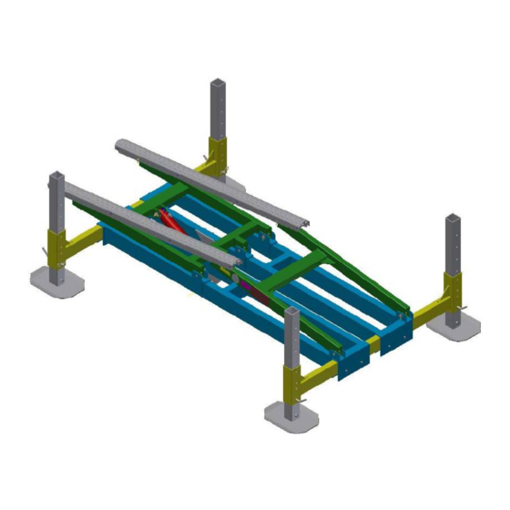
HL/VL10K LEG PIN 4" 4100505 HL FOOT PLATE 12X16-FORMED SQ, (2&3-3/16) 4107534 HL1.75K-HL2K LEG ASSY WLDMT 67.5 4107565 (4107586 on HL20058) PIN, CLEVIS 7/8 X 4-1/8 SS 4107913 HL CLEVIS PIN 7/8X7-1/16 SS 4107919 HL A/V BUNK WASHER 1 OD X 3/16 4107946 HL CYL SPACER 2"X29/32"X3/16"... - Page 19 Figure 7-2: Complete HL Hydraulic Lift Assembly...
-
Page 20: Limited Product Warranty
Marine Products RGC Marine products, hereafter referred to as the “Manufacturer”, extend this limited warranty to the original purchaser of this product. The original purchaser, hereinafter referred to as the “Buyer”, is defined as the first legal owner of this product other than an authorized distributor or dealer who has bought the product from the Manufacturer for resale to the public. - Page 21 F. NO EXTENSION OF STATUTE OF LIMITATIONS ANY REPAIRS PERFORMED UNDER EITHER OF THESE WARRANTIES SHALL NOT IN ANY WAY EXTEND THE ONE-YEAR AND FIFTEEN-YEAR STATUTES OF LIMITATIONS CONTAINED IN THIS LIMITED WARRANTY. G. PROCEDURE FOR WARRANTY PERFORMANCE If the product fails to perform to the Manufacturer’s specifications, the Buyer must contact the dealer from whom the product was purchased.
-
Page 22: Commercial Product Provisions
N. NO AUTHORITY TO ALTER WARRANTY No agent, representative, distributor or dealer has any authority to alter the terms of this warranty in any way. O. SPECIFIC LEGAL RIGHTS This warranty gives you specific legal rights and you may also have other rights, which vary, from State to State. COMMERCIAL PRODUCT PROVISIONS II. - Page 23 THESE EXPRESS WARRANTIES ARE IN LIEU OF AND EXCLUDE ANY AND ALL OTHER WARRANTIES, EXPRESS OR IMPLIED, INCLUDING, BUT NOT LIMITED TO, THE IMPLIED WARRANTIES OR MERCHANTABILITY AND FITNESS FOR A PARTICULAR PURPOSE. H. PROCEDURE FOR WARRANTY PERFORMANCE If the product fails to perform to the Manufacturer’s specifications, the Buyer must contact the dealer from whom the product was purchased.
Need help?
Do you have a question about the HL20058 and is the answer not in the manual?
Questions and answers