Tigo EI Installation Manual
Residential solar solution
Hide thumbs
Also See for EI:
- Installation manual (77 pages) ,
- Quick start manual (4 pages) ,
- Installation manual (52 pages)

Subscribe to Our Youtube Channel
Related Manuals for Tigo EI


Summary of Contents for Tigo EI
- Page 1 Tigo EI Residential Solar Solution US Installation Manual (w/ATS 50A) Visit the Tigo Energy Help Center for comprehensive videos, articles, and other resources for all Tigo products.
- Page 2 ENTIRE OBLIGATION OF TIGO. THE CONTENTS OF THIS DOCUMENT SHALL NOT BECOME PART OF, OR MODIFY ANY CONTRACT BETWEEN, THE PARTIES. In no event will Tigo be responsible to the purchaser or user in contract, in tort (including negligence), strict liability or otherwise for any special, indirect, incidental, exemplary, reliance...
-
Page 3: Table Of Contents
Inverter Connections ........................ 22 Power Connections ........................23 Current Transformer Connections ....................24 LED Indicators ......................... 25 Power Status LED ......................... 25 L1/L2 Phase Status LED......................25 Reset Button ..........................25 The EI Automatic Transfer Switch (ATS) ..................26 Box Contents ........................... 26... - Page 4 Add Batteries ........................... 37 Status Indicators ........................41 Forced Start/Shutdown ......................42 TAP and TS4 MLPE ........................43 Install the Tigo Access Point (TAP) .................... 43 Install TS4 MLPE ........................46 Commissioning ..........................48 Check Connections ........................48 Power On the System ....................... 48 Run the Tigo Energy Intelligence App ..................
- Page 5 Specifications ........................... 62 Warranty ..........................62 Customer Support ........................63 Appendix A – UL 1741 PCS CRD Section 208 Information ..............64 Integrations ..........................64 Time of Use ..........................65 Self-Consumption ........................66 Backup ............................ 66 Zero Export ..........................67 Appendix B –...
-
Page 6: Overview
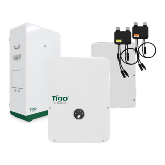
It’s built with the following components: 1. EI Inverter – A 3.8 kW or 7.6 kW hybrid inverter may be installed grid-tied only or as part of an energy storage system (ESS) when paired with up to four Tigo EI batteries. -
Page 7: This Manual
Overview – This Manual This Manual This manual provides instructions for installing the following components of a complete Tigo EI Residential Solution: • EI Inverter • Energy Meter • EI ATS 50A EI Battery • TS4 MLPE • EI Residential Solar Solution US Installation Manual... -
Page 8: Important Safety Information
IMPORTANT SAFETY INFORMATION – SAVE THESE INSTRUCTIONS IMPORTANT SAFETY INFORMATION SAVE THESE INSTRUCTIONS Together, the Tigo EI Inverter with the provided rapid shutdown switch and TS4-A-O/S/F/2F MLPE enable a photovoltaic rapid shutdown system (PVRSS) as defined by NFPA 70, National Electrical Code (NEC). - Page 9 National Electric Code (NEC) ANSI/NFPA 70 and/or local electrical codes. When the photovoltaic array is exposed to light, it supplies a DC voltage to the Tigo TS4 units and the output voltage may be as high as the PV module open circuit voltage (V ) when connected to the module.
- Page 10 Risk of electrical shock. Risk of burns. Check the operating instructions. Caution, the inverter may retain high voltage for up to five minutes after disconnection. Avoid tampering. Observe caution. Grounding connection. EI Residential Solar Solution US Installation Manual | www.tigoenergy.com Help Center...
-
Page 11: Pre-Installation
Pre-Installation – Location Pre-Installation Location EI enclosures are NEMA 4/IP65 rated for indoor and outdoor exposure. To optimize performance and extend service, locate the enclosures: In a well-ventilated, easily accessible location. • ° • On a flat surface against a solid wall with ≤15 tilt. -
Page 12: Component Dimensions
650 x 1160 x 320 mm (25.6 x 45.7 x 12.6 in.) 140kg (308.6 lb.) Wiring Overview The EI system can operate on 208 or 240 V at 60 Hz. For detailed wiring instructions, refer to the following Inverter, ATS,... -
Page 13: The Ei Inverter
• Mounting Communications Connections • Power Connections • • Rapid Shutdown Switch For detailed specifications, download the EI Inverter data sheet from the tigoenergy.com Downloads page. Box Contents The EI Inverter box includes: EI Inverter • Quick Start Guide •... -
Page 14: Dc Disconnect And Enclosure Knockouts
The EI Inverter – Enclosure Overview DC Disconnect and Enclosure Knockouts Status Indicators The status indicator LEDs in the center of the inverter front panel show the EI system’s current operating conditions. Symbol Action Description Continuous Feed in grid Flashing 3 sec. on/1 sec. off DC on/AC off Flashing 1 sec. -
Page 15: Mounting
1. Choose a location on a plumb wall with adequate clearance, free from direct sun and precipitation. 2. Affix the inverter top bracket using screws appropriate for the wall surface. EI Residential Solar Solution US Installation Manual | www.tigoenergy.com Help Center... -
Page 16: Communications Connections
Communications Connections CAUTION! You must make communications connections to the TAP (if used), Energy Meter, and battery for the EI system to operate as an energy storage system (ESS). Inverter communications connections include: • An antenna to connect to a WiFi or cell network. - Page 17 (4-wire or CAT5/6). 3. At the inverter, terminate the wires at the 4-pin TAP plug from bottom to top: –, +, Data B, Data A. EI Residential Solar Solution US Installation Manual | www.tigoenergy.com Help Center...
- Page 18 To connect to the Energy Meter: 1. Prepare a 3-wire shielded, twisted pair, 24-18 AWG RS-485 cable. Accessories 2. Locate the 3-pin plug included in the EI Inverter bag. 3. At the inverter, connect the RS-485 wires to the , and terminals on the 3-pin plug and install the plug.
- Page 19 CAT5/6 cable into the terminal. 2. At the inverter, plug the cable into the battery COM terminal. Battery Inverter To connect COM cables to multiple batteries, refer to the EI Battery section. EI Residential Solar Solution US Installation Manual | www.tigoenergy.com Help Center...
-
Page 20: Power Connections
The EI Inverter – Power Connections Power Connections DANGER! Ensure the inverter DC disconnect switch is OFF before making connections. Grounding Points Equipment grounding conductor (EGC): Grounding electrode conductor (GEC): EI Residential Solar Solution US Installation Manual | www.tigoenergy.com Help Center... -
Page 21: Wiring
AC (grid or ATS): 8 – 6 AWG • DC (PV): 12 – 8 AWG • DC (battery): 12 – 8 AWG DANGER! Always calculate conductor AWG based on wire length and current load. EI Residential Solar Solution US Installation Manual | www.tigoenergy.com Help Center... - Page 22 3.8 kW inverter: 20 A 2-pole breaker • 7.6 kW inverter: 40 A 2-pole breaker • INPUT INV L1 3. At the ATS, connect conductors to the terminals and the ground bar. Inverter EI Residential Solar Solution US Installation Manual | www.tigoenergy.com Help Center...
- Page 23 3.8 kW (2 MPPT) inverter: up to two strings 7.6 kW (3 MPPT) inverter: up to three strings • 3. Connect the PV array rack EGC to the inverter EGC busbar. EI Residential Solar Solution US Installation Manual | www.tigoenergy.com Help Center...
- Page 24 BAT+ BAT– terminals. BAT+ BAT– 2. Connect the conductors to the inverter terminals. Battery Inverter For details on how to add more batteries, refer to the EI Battery section. EI Residential Solar Solution US Installation Manual | www.tigoenergy.com Help Center...
-
Page 25: Rapid Shutdown Switch
The EI Inverter – Rapid Shutdown Switch Rapid Shutdown Switch Together, the Tigo EI Inverter with the provided rapid shutdown switch and TS4-A-O/S/F/2F MLPE enable a photovoltaic rapid shutdown system (PVRSS) as defined by NFPA 70, National Electrical Code (NEC). - Page 26 To connect a switch to multiple inverters, daisy-chain two 20 – 18 AWG wires to connect inverter switch terminals to the rapid shutdown switch. Inverter Inverter Inverter Rapid shutdown switch EI Residential Solar Solution US Installation Manual | www.tigoenergy.com Help Center...
-
Page 27: The Energy Meter
To connect the Energy Meter to the inverter: 1. Prepare a 3-wire shielded, twisted pair, 24-18 AWG RS-485 cable. Accessories 2. Locate the 3-pin plug included in the EI Inverter bag. 3. At the inverter, connect the RS-485 wires to the... -
Page 28: Power Connections
ØL1 ØL1 3. At the Energy Meter, connect the RS-485 wires to the , and terminals. Tighten set screws to 0.4 Nm. EI Residential Solar Solution US Installation Manual | www.tigoenergy.com Help Center... -
Page 29: Current Transformer Connections
3. Place the other CT around the L2 power conductor with the arrow pointing towards the grid. 4. Connect its blue and brown wires to the L1 and CT terminals at the top of the meter. EI Residential Solar Solution US Installation Manual | www.tigoenergy.com Help Center... -
Page 30: Led Indicators
Check line voltages and meter rating. Yellow – on for <3 sec. Frequency is <45 Hz Check for high noise. or >70 Hz Reset Button To update meter firmware, contact Tigo Support. EI Residential Solar Solution US Installation Manual | www.tigoenergy.com Help Center... -
Page 31: The Ei Automatic Transfer Switch (Ats)
The EI Automatic Transfer Switch (ATS) – Box Contents The EI Automatic Transfer Switch (ATS) This section includes: Box Contents • Enclosure Overview • • Mounting Wiring • Status Indicators • For detailed specifications, download the ATS data sheet from the tigoenergy.com Downloads page. -
Page 32: Mounting
The EI Automatic Transfer Switch (ATS) – Mounting Mounting To mount the ATS: 1. Choose a location on a plumb wall with greater than 12in clearance and free from direct sun and precipitation. 2. Use screws appropriate for the wall surface to affix the bracket and hang the ATS. -
Page 33: Wiring
The EI Automatic Transfer Switch (ATS) – Wiring Wiring AC conductors must be ferruled copper, 90 °C rated, non-fine stranded, 8 – 6 AWG. DANGER! Always calculate conductor AWG based on wire length and current load. Backup Load Connections To connect the ATS to the backup load panel: OUTPUT LOAD L1, N, 1. -
Page 34: Grid Connections
The EI Automatic Transfer Switch (ATS) – Wiring Grid Connections This connection carries power between the utility grid and the ATS. Direct connection to utility feeders or a line side may require coordination with the local utility. To connect the ATS to the main panel: INPUT GRID L1, N, 1. -
Page 35: Inverter Connections
The EI Automatic Transfer Switch (ATS) – Wiring Inverter Connections GRID To connect to the inverter terminals: GRID L1 1. Connect conductors to the inverter terminals and the ground bar. INPUT INV L1 2. At the ATS, connect conductors to the terminals and the ground bar. -
Page 36: The Ei Battery
The EI Battery – Box Contents The EI Battery An EI system may include one, two, or four battery enclosures. This section includes: Box Contents • Enclosure Overview • • Place and Prepare Connect to the Inverter • Add Batteries •... -
Page 37: Enclosure Overview
A plumb wall. • Minimum 914 mm (3 ft.) clearance side-to-side and top. • • No direct sun or precipitation. 2. If mounting against a wall, affix the two side tabs. EI Residential Solar Solution US Installation Manual | www.tigoenergy.com Help Center... - Page 38 Lower inner bat Link-Out 9. In the lower section, connect the loose cable to the inner Link Out Link In (back) module terminal and the outer (front) module terminal. EI Residential Solar Solution US Installation Manual | www.tigoenergy.com Help Center...
- Page 39 10. Connect the other cables according to their labels. CAN/COM 11. Insert an RJ45 terminator in the port located in the battery expansion wirebox on the enclosure right side. EI Residential Solar Solution US Installation Manual | www.tigoenergy.com Help Center...
-
Page 40: Connect To The Inverter
The EI Battery – Connect to the Inverter Connect to the Inverter To connect battery power conductors to the inverter: 1. In the inverter connection wirebox on the enclosure left side, connect two ≤2m/6’7in BAT+ BAT– conductors to the terminals. - Page 41 The EI Battery – Connect to the Inverter To connect the battery COM cable to the inverter: COM INV 1. In the battery inverter connection wirebox, plug the COM cable into the port. 2. Plug the cable into the inverter battery port.
-
Page 42: Add Batteries
To add one battery in parallel: 1. In the battery expansion wireboxes, connect an RJ45 (CAT5/6 T586B) cable from the COM Parallel COM Parallel battery #1 plug to the battery #2 plug. EI Residential Solar Solution US Installation Manual | www.tigoenergy.com Help Center... - Page 43 2. Connect two ≤2.5 m (92 in.) conductors between the battery #2 BAT+ and BAT– terminals and the inverter BAT terminals. 12. In the battery expansion wireboxes, connect a terminator to each CAN/COM terminal. EI Residential Solar Solution US Installation Manual | www.tigoenergy.com Help Center...
- Page 44 5. In the battery expansion wireboxes, connect power conductors between the BAT– terminals on batteries #2 and #4. 6. In the battery expansion wireboxes, connect terminators to CAN/COM terminals on batteries #3 and #4. EI Residential Solar Solution US Installation Manual | www.tigoenergy.com Help Center...
- Page 45 The EI Battery – Add Batteries To add one battery with a serial connection (EI Battery part number 603-00000-10 only): 1. Inside the battery enclosures, connect a COM cable from the battery #1 lower outer COM Link Out COM Link In...
-
Page 46: Status Indicators
≤75% – 1, 2 on, 3 flashes; 4 off ≤75% – 1, 2, 3 on; 4 off ≥75% – 1, 2, 3 on; 4 flashes ≥75% – 1, 2, 3, 4 on EI Residential Solar Solution US Installation Manual | www.tigoenergy.com Help Center... -
Page 47: Forced Start/Shutdown
The leaf status indicator starts flashing green (0.1 sec. on/0.1 sec. off). 3. To force a shutdown, press the power button for 10 sec. The leaf status indicator starts flashing red (0.1 sec. on/0.1 sec. off). 4. Reinstall the cover. EI Residential Solar Solution US Installation Manual | www.tigoenergy.com Help Center... -
Page 48: Tap And Ts4 Mlpe
TAP and TS4 MLPE – Install the Tigo Access Point (TAP) TAP and TS4 MLPE Install the Tigo Access Point (TAP) Installations equipped with TS4-A-O/S MLPE require a wired TAP connection to the inverter. A TAP wirelessly communicates with TS4 devices to gather data and perform rapid shutdowns. - Page 49 TAP and TS4 MLPE – Install the Tigo Access Point (TAP) To install a TAP: 4. Prepare a 4-wire or CAT5/6 cable: Shielded if running next to PV conductors • 20 – 18 AWG or CAT5/6 twisted pairs • •...
- Page 50 TAP and TS4 MLPE – Install the Tigo Access Point (TAP) 8. Run the CAT5/6 cable through the inverter left COM knockout and connect to the 4-pin connector. EI Residential Solar Solution US Installation Manual | www.tigoenergy.com Help Center...
-
Page 51: Install Ts4 Mlpe
TAP and TS4 MLPE – Install TS4 MLPE Install TS4 MLPE To install TS4 devices and map them for the Tigo Energy Intelligence app: 1. Attach a TS4 device to a PV module frame using the silver clips. If using frameless modules, remove the clips and bolt the TS4 directly to the PV rail with M8 bolts. - Page 52 2. Remove the barcode sticker on the TS4 and place it on the PV array map located at the end of the EI Inverter Quick Start Guide. Ensure the sticker matches the physical location of the module on the roof.
-
Page 53: Commissioning
4. If the inverter does not start, force-start the battery by removing the start button cover and pressing until the green leaf status LED flashes rapidly. 5. Ensure Bluetooth is enabled on your mobile device, open the Tigo EI app, and tap + to create a new system. -
Page 54: Run The Tigo Energy Intelligence App
Scan one of these QR codes to download the app. To run the Tigo EI app and commission the system, first ensure Bluetooth is enabled on your mobile device. Do not try to select your system using your mobile device’s Bluetooth settings. The EI app will automatically connect to your system. -
Page 55: Select Equipment
The first component discovered is the EI Inverter or, in some cases, the Cloud Connect Advanced (CCA) component. 3. After a component is discovered or entered manually, tap EI Residential Solar Solution US Installation Manual | www.tigoenergy.com Help Center... - Page 56 Grid 7. Tap Inverter Settings, select the Code Advanced Options, , configure Save AC Meter, Battery Settings Main Breaker Limit 8. Configure , and options as needed. EI Residential Solar Solution US Installation Manual | www.tigoenergy.com Help Center...
- Page 57 You may scan bar codes located on enclosures or on boxes. PV Modules 11. Tap the back arrow and tap to set up the PV array and Tigo TS4 devices. EI Residential Solar Solution US Installation Manual | www.tigoenergy.com Help Center...
- Page 58 , and Save Modules count and tap Done 14. Repeat these steps for as many strings as needed and tap 15. Review your entries and tap the back arrow. EI Residential Solar Solution US Installation Manual | www.tigoenergy.com Help Center...
-
Page 59: Configure Layout
You may also configure layout using a large monitor via the EI portal. Click Tigo EI Login at www.tigoenergy.com and use your EI app credentials. However, you can only complete commissioning using the mobile app. EI Residential Solar Solution US Installation Manual | www.tigoenergy.com... - Page 60 Arrange the modules carefully to reflect their actual • layout on a roof or field. Tap a module to change its portrait/landscape orientation. EI Residential Solar Solution US Installation Manual | www.tigoenergy.com Help Center...
- Page 61 If, during installation, you affixed barcode/QR code stickers from each TS4 to the • array map included in the EI Inverter Quick Start Guide, you may use the Bulk Scan method. You may scan each TS4 barcode/QR code with your smartphone.
- Page 62 8. Verify that all modules are oriented consistently – portrait or landscape. Tap a module repeatedly to alternate orientation. 9. Tap the back arrow to return to the commissioning screen. EI Residential Solar Solution US Installation Manual | www.tigoenergy.com Help Center...
-
Page 63: Configure Communication
System Access 1. Tap to set access permissions. 2. Tap the Add icon to enter data for whoever will be accessing the system such as the installer and system owner. EI Residential Solar Solution US Installation Manual | www.tigoenergy.com Help Center... -
Page 64: Reference
• • Warranty Error Codes Select Equipment > Inverters > View To view error codes, open the EI app and navigate to the Details> Configure Inverter Details Connect screen and tap CAUTION! Shut down the system before checking PV module or system wiring. -
Page 65: Inverter Fault Codes
DSP and M3 firmware. 3. Change the DSP or M3 board. The data sampled by the DSP and redundant Restart the inverter. M3 are not the same. GFCI fault Restart the inverter. EI Residential Solar Solution US Installation Manual | www.tigoenergy.com Help Center... -
Page 66: System Fault Codes
3. Verify grid frequency is within allowable tolerance (59.3 to 60.8 Hz). 4. Restart the inverter. Auto test failed The EI Inverter initial auto test 1. Restart the inverter. has failed. 2. Repeat auto test. 3. Check all connections and wiring. -
Page 67: Decommissioning
Maintain proper clearances around all enclosures to ensure proper air circulation. • Check enclosures quarterly and remove any insects and rodent nests. • Specifications Download comprehensive specifications for all Tigo products from the Tigoenergy.com Downloads (www.tigoenergy.com/downloads) page. Warranty Download comprehensive warranty information from the Tigoenergy.com Downloads (www.tigoenergy.com/downloads) page. -
Page 68: Customer Support
When you contact Tigo support for installation or operational assistance: • If the system is commissioned and connected to the internet, Tigo will have component- level data to help understand and resolve the issue. If you have not yet commissioned the system, you’ll need to know your System ID as •... -
Page 69: Appendix A - Ul 1741 Pcs Crd Section 208 Information
Appendix A – UL 1741 PCS CRD Section 208 Information – Integrations Appendix A – UL 1741 PCS CRD Section 208 Information The major system elements making up the Tigo power control system (PCS) include: A hybrid inverter: TSI-3.8K-US, TSI-7.6K-US, or TSI-11.4K-US •... -
Page 70: Time Of Use
2. Adjust the sliders to set when utility rates are highest, when the battery can be charged from the grid, and a desired battery reserve during peak periods (how much energy to save in case of grid failure). EI Residential Solar Solution US Installation Manual | www.tigoenergy.com Help Center... -
Page 71: Self-Consumption
This mode controls the battery reserve to enable maximizing backup energy in case of an outage. Backup To configure settings: Energy/Battery Management > System Behavior > Backup 1. Select Backup 2. Tap the control. EI Residential Solar Solution US Installation Manual | www.tigoenergy.com Help Center... -
Page 72: Zero Export
Edit System > Select Equipment > Inverter > View Details > Connect > Inverter 1. Select Settings > Grid Code > Advanced Options > AC Meter Export Power Allowed 2. Toggle off the setting. EI Residential Solar Solution US Installation Manual | www.tigoenergy.com Help Center... -
Page 73: Appendix B - Configuring Heco Requirements
Settings > Edit System > Select Equipment > Inverter > View Details > Connect 2. Select > Inverter Settings > Grid Code > Advanced Options > AC Meter Export Power Allowed 3. Toggle off the setting. EI Residential Solar Solution US Installation Manual | www.tigoenergy.com Help Center...
Need help?
Do you have a question about the EI and is the answer not in the manual?
Questions and answers