Advertisement
Quick Links
1. General Information – Specifications
ATTENTION - READ FIRST
!
1.
This document is for quick guidance only. For details, please refer to the Energy Intelligence (EI) Inverter Installation & Operations Manual.
2.
Damage caused by failure to follow the contents of the EI Inverter Installation & Operations Manual is not covered by the warranty.
3.
Before installing the system, check that the package contents are intact and complete against the packing list. If any damage is found or any component is
missing, contact your dealer.
1.1 Package Contents
1.2 AC Wiring Diagram
Item
Quantity
EI Inverter
1
Quick Start Guide
1
Mounting bracket
1
Tigo Access Point (TAP)
1
Rapid shutdown label
1
E-Stop button
1
L1 N L2
DC wire ferrules
4 per MPPT
Battery wire ferrules
4
AC wire ferrules
5
3-pin connector
1
Grounding ring terminal
1
Hex-head self-tapping screws (inverter mounting)
5
Phillips-head screws (E-Stop mounting)
4
G
White wall anchors (inverter)
5
Backup Panel
Green wall anchors (E-Stop)
4
WiFi antenna
1
Cellular antenna (only in cell-enabled models)
1
¾" conduit hole plug with nut
1
1" conduit hole plugs with nuts
2
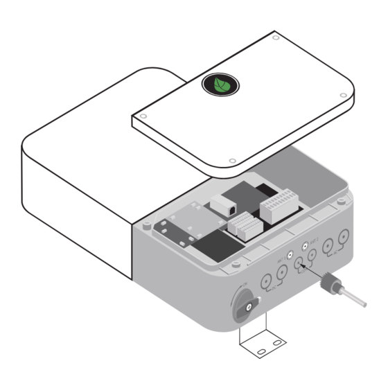
1.3 Overview
1
2
3
4
5
1. Front panel
4. DC disconnect switch
2. LED indicators
5. PV input
3. Wiring box cover
6. Battery input
2. Installation
2.1 Installation Requirements
1.
Do NOT install the inverter in the direct sun, rain, or snow.
2.
If installing more than one inverter, refer to the EI Inverter
Installation & Operations Manual for clearances.
Item
W (inch/mm) H (inch/mm)
D (inch/mm)
TSI-3.8K-US
15.75/400
22.4/570
7/170
TSI-7.6K-US
15.75/400
22.4/570
7/170
TSI-11.4K-US
15.75/400
25.2/638
7.4/187
Energy Meter
EI Inverter
ATS
CT L1 CT L2
AC Grid
Input
+
–
-
+ –
L1 N L2
Backup
Panel
Inv Grid Inv
ATS
EGC
AC Grid
L1 L1 L2 L2
L1 N L2
L2 L1
N
6
7
8
9
10
11
12
13
10. Battery com input
1 3 . External grounding point
7. WiFi antenna port
8. Cellular antenna port
11. Backup output
1 4 . M o u n t i n g b ra c k e t
12. AC grid output
1 5 . H e a t s i n k
9 . TA P / M e t e r / R S D i n p u t
≥12"
≥12"
≥12"
2.2 Prepare Conduit Openings
1 . Determine which inputs/ports will need to be opened.
References in
Label on
Guides
Inverter
PV input
DC (left side)
Battery input
DC (right side)
Comm
COM (left side)
Comm
COM (right side) 10
Backup output
AC (left side)
AC grid output
AC (right side)
2.3 Mounting
CAUTION – Use appropriate hardware
!
for the mounting surface.
Grid
Meter
N
G
Main Panel
3.2 Connections
3.2.1 Pressure Terminals
1.
Insert a 1/8" flat blade screwdriver in the
terminal at a right angle to the terminal face.
Press the clamp open by tilting down.
2.
Insert the conductor into the terminal's round
opening.
3.
Remove the screwdriver to release the clamp
and secure the conductor.
4.
Gently tug the conductor to ensure it is secure.
3.3 Inverter Output Connection – GRID
1.
Run AC grid conductors through the AC grid output opening (12).
2.
Terminate the AC grid conductors at the appropriate terminals.
L2
L1
L1
Backup
3.
Connect the AC EGC to the grounding busbar.
4.
Terminate the opposite end of the inverter output conductors at the main
service panel with the appropriately sized OCPD.
14
15
EI Inverter Model
TSI-3.8K-US
TSI-7.6K-US
TSI-11.4K-US
3.4 Backup Output Connection – Battery Systems Only
1.
Install the AC conduit to the AC grid output opening (11).
Use appropriate conduit fittings and bond where necessary.
Run AC backup conductors.
2.
Terminate the AC backup conductors at the appropriate
terminals.
L2
L1
L1
≥12"
Backup
3.
Connect the AC EGC to the grounding busbar.
4.
The opposite ends of the backup conductors terminate at
the ATS. To complete ATS connections at this time, refer to
the ATS manual.
Quick Start Guide – TSI-3.8/7.6/11.4K-US
2. Remove the wire box cover (3)
using a 3/16" (5mm) screwdriver.
# on
Drill/If installing
3. With a hole saw, CAREFULLY
Diagram
open the conduit drill guide for the
5
Yes
necessary openings.
6
Yes/battery
9
Yes/TAP or meter
Yes/battery
11
Yes/ATS
12
Yes
3. Electrical Connections
CAUTION – Check that all Disconnect switches are OFF
!
before wiring. For personal safety, do not operate with
electricity and always wear appropriate PPE.
3.1 Wire Schedule/Preparation
1.
To prepare the DC conductors (PV+, PV-, and BAT), strip 5/8"/16mm of the DC connector's
jacket and crimp on the DC wire ferrule.
2.
To prepare the AC conductors (GRID and BACKUP), strip 0.7"/18mm of the AC conductor's
jacket and crimp on the AC wire ferrule.
Use
Equipment grounding conductors Yellow-green jacketed or solid bare copper
AC output conductors
Multi-color jacket, copper
(BACKUP/GRID)
PV input conductors
Red/Black photovoltaic wire (ex: PV1-F)
Battery input conductors
Red/Black photovoltaic wire (ex: PV1-F)
3.2.2 Screw Terminals
1.
Insert the equipment grounding
conductor (EGC) into the grounding
busbar.
2.
Use a #2 Phillips screwdriver to
tighten the set screw and secure the
EGC.
3.
Gently tug the conductor to ensure
it is secure.
N
L2
Grid
Over Current Rating
20A (bi-directional)
40A (bi-directional)
60A (bi-directional)
N
L2
Grid
EI Inverter
Pg. 1 of 4
Type
Size
10 - 8 AWG
8 - 6 AWG
10 - 8 AWG
12 - 8 AWG
PN: 002-00078-00 | Rev. 2.0 | Dec. 20, 2022
Advertisement

Subscribe to Our Youtube Channel
Related Manuals for Tigo TSI-3.8K-US


Summary of Contents for Tigo TSI-3.8K-US
- Page 1 Quick Start Guide Mounting bracket Energy Meter EI Inverter 3. Electrical Connections 2.3 Mounting Tigo Access Point (TAP) Rapid shutdown label CT L1 CT L2 AC Grid CAUTION – Use appropriate hardware CAUTION – Check that all Disconnect switches are OFF Input –...
- Page 2 RJ-45 Male Plug Scan here for TS4 downloads 3.6 PV Connections NOTE: The TSI-3.8K-US has 2 MPPTs, the TSI-7.6K-US has 3 MPPTs, and the TSI-11.4K-US has 4 MPPTs. Install the PV conduit to the DC PV input opening (5). Use appropriate conduit fittings and bond where necessary.
- Page 3 Ensure the E-Stop button (if used) is not in the depressed position. the signal conductors. Open the Tigo EI app to complete commissioning by making all required inverter and battery settings. Connect the conductors to the switch as shown. Reinstall the switch cover and tighten the plastic screws to secure.
- Page 4 EI Inverter Quick Start Guide – TSI-3.8/7.6/11.4K-US Pg. 4 of 4 Place TS4-A-O barcode stickers in the grid below per system azimuths and layouts for scanning into the EI app. Examples: PN: 002-00078-00 | Rev. 2.0 | Dec. 20, 2021...
Need help?
Do you have a question about the TSI-3.8K-US and is the answer not in the manual?
Questions and answers