Tigo TS4-A-O Quick Start Manual
Hide thumbs
Also See for TS4-A-O:
- Quick start manual (3 pages) ,
- Installation & quick start manual (2 pages) ,
- Manual (2 pages)
Table of Contents
Advertisement
Quick Links
• Do not install TS4s if they have been physically damaged or with damaged or
substandard wiring or connectors.
• Do not connect or disconnect TS4s under load.
• When used as a PVRSS solution, all solar modules in the array must be
equipped with TS4-A-O/S and TAP PVRSE with a permanent or temporary (for
commissioning) CCA. Rapid shutdown is initiated upon AC power loss that stops
power to the TAP.
System Layout
CCA
TAP
• The Cloud Connect Advanced (CCA) data logger/gateway connects to the cloud via Ethernet
or WiFi and to other devices via Modbus.
• The CCA has a wired connection to the Tigo Access Point (TAP).
• The TAP communicates wirelessly with TS4-A-O/S/M MLPE via a mesh network.
TS4 Mounting Options
For frameless modules, use M8 bolts torqued to 10.2Nm.
Removable
spring clips
M8 bolt holes
TS4-A-O/S/M with TAP and CCA
Visit the TigoEnergy.com
Help Center
TS4s
Frame thickness
If frame thickness is ≤35mm (1.4in), install
with the TS4 label facing the PV module.
Quick Start Guide
and
Downloads
pages for comprehensive videos, articles,
and other resources for all Tigo products.
Install TS4s
1. Save the QR/barcode sticker on a site map or
string list.
2. Attach the TS4 to the top of the PV module frame.
If frame thickness is ≤35mm (1.4in), install with the
TS4 label facing the PV module.
3. Connect the short input cables to the PV module.
4. Connect the long output leads to the adjacent TS4.
• All PVRSE components must be installed and
maintained by qualified personnel in accordance with
applicable electrical codes and instructions in the
TS4-A with CCA and TAP Installation
• Improper installation may cause damage not covered
by the warranty.
• Adhere to ANSI/NFPA 70 (North America) and local
electrical code requirements.
• Always assume that TS4s are in an ON state.
• Ensure cable glands face down and cannot collect moisture.
• Disconnect TS4s from the array string before disconnecting
from a PV module.
• Always connect short input cables before connecting
long output cables. Failure to do so may void warranty.
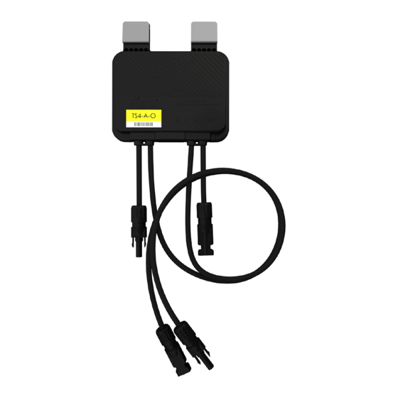
Output
Output
cable
cable
(long)
(long)
©20230515 Tigo Energy, Inc.
Manual.
Cable locations
may vary
by model
Input
Input
cable
cable
(short)
(short)
*002-00147-00*
002-00147-00 Rev. 1.1
Advertisement
Table of Contents

Related Manuals for Tigo TS4-A-O


Summary of Contents for Tigo TS4-A-O
- Page 1 2. Attach the TS4 to the top of the PV module frame. • Disconnect TS4s from the array string before disconnecting equipped with TS4-A-O/S and TAP PVRSE with a permanent or temporary (for If frame thickness is ≤35mm (1.4in), install with the from a PV module.
- Page 2 TS4 PV conductors are 12 AWG. The combination of TS4-A-O/S with TAP and CCA is certified as a UL 1741 photovoltaic rapid shutdown system (PVRSS) within a rapid shutdown time limit of 30s. The CCA data logger/gateway (P/N 346-00000-00) is powered from the same AC circuit as the rapid shutdown initiator (RSI) circuit.
Need help?
Do you have a question about the TS4-A-O and is the answer not in the manual?
Questions and answers