Advertisement
Table of Contents
- 1 Table of Contents
- 2 Pre-Installation Considerations
- 3 Cautions & Warnings
- 4 Component Mounting
- 5 Wiring Information
- 6 Power Door Lock Wiring, Systems & Diagrams
- 7 Tachless, Tach Reference, Tach Finder, Timed Crank Modes
- 8 Diesel Glow Plug Delay
- 9 Programmable Options, Options Reset
- 10 Remote Transmitter / Transceiver Programming (1-Way & 2-Way Remotes)
- 11 2-Vehicle Operation
- 12 Alarm Trigger Diagnostics
- 13 Remote Start Diagnostics
- 14 Jumper Pin Diagram
- 15 Antenna Diagram, System Wiring Diagram, DATA Port Diagram
- Download this manual
CS-2012DP-TW1 / CS-2014DP-TW2-FM / CS-2016DP-FM
Congratulations on your choice of a Crimestopper combination alarm & remote engine starter with Data Port
Technology. This installation Handbook covers the following DP Series II models: CS2011DP, CS-2012DP-TW1,
and CS-2014DP-TW2-FM & CS-2900DP-FM.
This installation book is designed for the installer or individual with an existing understanding of
automotive electrical systems, along with the ability to test and connect wires for proper operation. To ease
installation, we suggest that you READ THIS MANUAL before beginning your installation. This book is
provided as a GENERAL GUIDELINE and the information contained herein may differ from your vehicle.
DISCLAIMER:
Crimestopper Security Products, Inc. and its vendors shall not be liable for any accident resulting from the
use of this product. This system is designed to be professionally installed into a vehicle in which all
systems and associated components are in perfect working condition.
TECHNICAL SUPPORT (800)-998-6880
Monday - Friday 8:00am - 4:30pm Pacific Time
Website: www.crimestopper.com
CRIMESTOPPER SECURITY PRODUCTS, INC.
1770 S. TAPO STREET
SIMI VALLEY, CA. 93063
REV B 2.27.2007
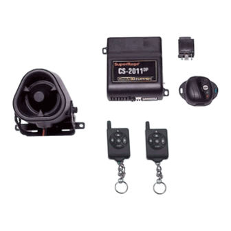
CS-2011DP One Way System
CS-2900DP-FM Alarm Combo System
DP Series II (2-Way Data Port)
INSTALLATION HANDBOOK:
INTRODUCTION
This device complies with FCC Rules part 15. Operation is
subject to the following two conditions: 1) This device may not
cause interference, and (2) this device must accept any
interference that may be received, including interference that
may cause undesired operation.
responsible for any radio or TV interference caused by
unauthorized
modification
modification could void the user's authority to operate the
equipment.
The manufacturer is not
to
this
equipment.
Such
Advertisement
Table of Contents

Subscribe to Our Youtube Channel
Related Manuals for CrimeStopper CS-2011DP


Summary of Contents for CrimeStopper CS-2011DP
- Page 1 GENERAL GUIDELINE and the information contained herein may differ from your vehicle. DISCLAIMER: Crimestopper Security Products, Inc. and its vendors shall not be liable for any accident resulting from the use of this product. This system is designed to be professionally installed into a vehicle in which all systems and associated components are in perfect working condition.
-
Page 2: Table Of Contents
TABLE OF CONTENTS Pre-Installation Considerations…………………...….…...…………...……………………………………………………….2 Cautions & Warnings…….…………………………..…..………………………………………………………………………3 Component Mounting………….……………………..……………………………………………….…………………..……..3 Wiring Information ………….…………………………..……………...……………………………………………..……4-12 Power Door Lock Wiring, Systems & Diagrams..….………………...….………..…….……..…………...……………13-15 Tachless, Tach Reference, Tach Finder, Timed Crank Modes………..……………………………………………..16-18 Diesel Glow Plug Delay………………………………………………………………………………………………...………19 Programmable Options, Options Reset……….………………………………………………….………….………...…19-25 Remote Transmitter / Transceiver Programming (1-Way & 2-Way Remotes)……..…………………...…...…...….25-26 2-Vehicle Operation……………………………………………………………………………………………………...……..27 Alarm Trigger Diagnostics…………………..…………………………………………………………………….………….28 Remote Start Diagnostics………….……………………..………………………………………...…………………...…….28... -
Page 3: Cautions & Warnings
CAUTIONS & WARNINGS DAMAGE RESULTING FROM IMPROPER INSTALLATION IS NOT COVERED UNDER WARRANTY!! DO NOT remote start your vehicle in a closed garage. Make sure that the garage door is open or there is adequate ventilation. Failure to observe this rule could result in injury or death from poisonous Carbon Monoxide fumes. DO NOT ROUTE ANY WIRING THAT MAY BECOME ENTANGLED with the brake/gas pedals, steering column, or any other moving parts in the vehicle. -
Page 4: Wiring Information
WIRING: 9-PIN Connector Green: MODE A: (-) Start Activation Input This wire allows an outside source or accessory to Optional Turbo Timer Wiring activate a Remote Start. A 1-second Ground pulse Momentary on this wire will trigger a remote start. This wire Switch can be used with an RS-400 temperature module. - Page 5 WIRING: 9-PIN Connector Cont. Green/Red: (-) 500mA Remote Aux. Output 1 (Optional, requires relay) This is a programmable output that can operate two different ways: 1. (DEFAULT) A Remote Auxiliary Output that provides a ½ second (-) Negative pulse when Button #3 is pressed to open a Factory power trunk or hatch release. NEGATIVE AUXILARY OUTPUT +12V CONSTANT GREEN/RED...
- Page 6 WIRING: 9-PIN Connector Cont. Blue/White: (-) Passenger Door Unlock Output (Optional, requires relay) This wire activates when the unlock button on the remote is pressed a second time within 15 seconds upon disarming. This wire is used for the Optional Separate Driver’s/Passenger Unlock feature. Connects to unlock circuit for passenger door or doors.
- Page 7 WIRING: 9-PIN Connector Cont. Orange/Black: (-) OEM Disarm Output This wire provides a Ground pulse to disarm vehicles' Factory anti-theft system prior to a Remote Start. Connect this wire to the vehicles' anti-theft disarm wire. This wire is sometimes found coming off the Driver's door key switch or at the Factory Anti-theft control module.
- Page 8 WIRING: 6-PIN High Current Connector Diagram not to scale, for illustration purposes only. Your vehicle may differ. FUSE FUSE PINK/WHITE PINK BROWN BATTERY FUEL ENGINE GRAY PUMP STARTER COIL START 2 IGN 2 ACC 2 Jumper Select HEAT / AC (page 30) NOTE! Use External Relays for High Current Ignition and/or Accessory circuits greater...
- Page 9 WIRING: 5-PIN Connector Violet: (+) Door Pin Switch Input Same as the GREEN wire below except this wire is used for vehicles that show a positive voltage (+12 volts) when the door is open and a ground when doors are closed as in many Ford, Lincoln, and Mercury vehicles. Green: (-) Door Pin Switch Input Identify the wire that reads ground when any door is open and 12 volts when all doors are closed.
- Page 10 WIRING: 5-PIN Connector OPTIONAL CAR JACK WIRING: HIDDEN BUTTON or IGN SW TOGGLE SWITCH + IGN (Not Included) 12 V PINK PINK CONTROLLED W/SWITCH FULL-TIME CARJACK White: (+12V) Brake Reset Connect the White wire to the side of brake pedal switch that shows +12 volts ONLY when pedal is depressed. This will turn off the remote start if someone attempts to drive the car without the keys or if the Ignition key is not turned on all the way.
- Page 11 WIRING: 4-PIN Shock Sensor (22 Gauge wires) Sensor Adjustment Adjust the main shock sensor with the small White dial. Clockwise will increase sensitivity and counter-clockwise will decrease sensitivity. Adjust Pre-Warning level with small Black dial. GREEN LED (Pre-Warn) (WHITE KNOB) TRIGGER PRE-WARN (BLACK KNOB)
- Page 12 WIRE: 4 PIN OUTPUT CONNECTOR YELLOW/BLACK: (-) OEM REARM OUTPUT This wire provides a ground pulse to rearm the vehicles' FACTORY anti-theft system after a timed-out or aborted remote start. Connect this wire to the vehicles' anti-theft rearm wire or to the door pin circuit depending on your requirements.
-
Page 13: Power Door Lock Wiring, Systems & Diagrams
POWER DOOR LOCKS: WIRING & SYSTEM TYPES GREEN: (-) LOCK / (+) UNLOCK BLUE: (-) UNLOCK / (+) LOCK [READ BELOW FOR COMMON DOOR LOCK TYPES] RED: +12V Coil Power for external relays HINT! This system provides BOTH Positive and Negative Door Lock Outputs on the same set of wires. Make note of this and use diodes when installing this system on either Positive or Negative types of door lock systems to prevent damage to the unit’s door lock outputs. - Page 14 DOOR LOCK WIRING NEGATIVE TRIGGER DOORLOCK WIRING POSITIVE TRIGGER DOORLOCK WIRING GREEN GREEN BLUE BLUE IN4001 IN4001 DIODES DIODES FACTORY FACTORY LOCK LOCK POWER POWER LOCKING LOCKING RELAYS RELAYS UNLOCK UNLOCK REVERSE POLARITY DOOR LOCK WIRING AFTERMARKET MOTOR/DOOR LOCK WIRING GREEN GREEN FUSED...
- Page 15 SEPARATE DRIVER’S DOOR UNLOCK WIRING NEGATIVE TRIGGER DOOR LOCKS BLUE/WHITE GREEN 1N4001 Diode BLUE DRIVER'S DOOR MOTOR FACTORY LOCK RELAYS +12V FUSED UNLOCK WIRE WIRING FOR REVERSE POLARITY DOOR LOCKS BLUE/WHITE GREEN FUSED +12V BLUE MASTER SWITCH 30 87A LOCK WIRE UNLOCK WIRE...
-
Page 16: Tachless, Tach Reference, Tach Finder, Timed Crank Modes
TACHLESS MODE Your system includes a Tach-less mode that actively monitors and compares the vehicle’s resting voltage versus its running voltage each a remote start is performed; [instead of the conventional tach-pulse method]. Smart Tachless mode adjusts automatically to maintain optimum efficiency over the life of the life of the installation. IMPORTANT NOTES: (1) SETUP may be required for the Tachless Mode. - Page 17 TACH MODE & TACH FINDER FEATURE Tach Reference Mode provides reliable remote starting performance though engine speed sensing. When using Tach Reference Mode, the WHITE/RED wire is used for Tach signal [Engine RPM] input. Most modern engines include various points where the Engine Speed [Tach] or A/C signal may be obtained. Tach Signal examples: Negative (-) side of ignition coil, at the Distributor or Ignition Control Module, Coil Pack, Engine Computer, or Crankshaft Sensor.
- Page 18 TIMED CRANK MODE As an alternative to Tach or Tachless mode, “Timed Crank” provides an additional method of starting the vehicle without locating an exact tach wire. It uses a timed cranking output combined with the use of the Red/White tach wire as an engine ON/OFF monitor.
-
Page 19: Diesel Glow Plug Delay
DIESEL GLOW PLUG DELAY This feature provides a solution for diesel vehicles without having to connect to the Glow Plug-“Wait to Start Circuit” input. This may be due to a variety of reasons for example: If your vehicle does not have a viable “Wait to Start Circuit”... - Page 20 OPTION PROGRAMMING TABLE Option Option Description TX Button #1 TX Button #2 TX Button #3 TX Button #4 Engine Monitoring Learn Tach *Tachless* Auto lock with Ignition *ON* Passive Arming Ignition and last door ON *OFF* Ignition only *Last Door* only With Ignition or Last Door Active Re-Arm *OFF*...
- Page 21 OPTION PROGRAMMING TABLE PINK Wire function Carjack *Glow Plug* Starter Cranking Time (Option #16 0.75 Sec. *0.5 Sec.* 1.0 Sec. 1.5 Sec. is set to Timed Crank) Diesel Glow Plug Delay 10 Seconds *Monitor Glow Plug 20 Seconds 30 Seconds Remote Start Engine Run Time 12 Minutes *24 Minutes*...
- Page 22 PROGRAMMABLE OPTIONS Cont. 4. ACTIVE RE-ARM: Active Re-arming allows the system to re-arm itself 30 seconds after disarmed with the transmitter if a door has not been opened. The status LED flashes rapidly during 30 second re-arm countdown. This is handy if the vehicle is accidentally disarmed without your knowledge. 5.
- Page 23 PROGRAMMABLE OPTIONS Cont. 12. DOOR LOCK/UNLOCK PULSE TIME: This option controls the amount of time (0.75 sec. or 3 sec.) for the lock/unlock pulse. The standard pulse time for most vehicles is 0.75 Sec. The 3 sec. setting may be required for Mid 1980’s through Mid 1990’s European Vehicles that require a long lock and unlock pulse to operate Vacuum door lock systems.
- Page 24 PROGRAMMABLE OPTIONS Cont. 21. PRE-SET STARTER CRANKING TIME: (Requires Option #16 in “Pre-Set” Setting) This option controls the starter cranking time when in “Timed Crank” Mode. Choices are 0.5, 0.75, 1.0, or 1.5 sec. 22. DIESEL GLOW PLUG DELAY This option controls the system’s Diesel vehicle interface. Using this option you can control whether the unit monitors the vehicle’s glow plug circuit using the Pink input wire (Default), or you may select a specific delay time Before cranking.
-
Page 25: Remote Transmitter / Transceiver Programming (1-Way & 2-Way Remotes)
PROGRAMMING – TRANSCEIVERS & TRANSMITTERS MAKE a NOTE of the following transmitter / transceiver compatibilities: • CS-2011DP 1-WAY SYSTEM: CS-511TX Remotes ONLY • CS-2012DP-TW1 2-Way System: CS-799LED Remote / CS-512TW “Sidekick” non-paging remote • CS-2014DP-TW2 2-Way System: CS-599FM LCD Remote / CS-519TW “Sidekick” non-paging remote •... - Page 26 NOTE: When learning 2-Way LCD or 2-Way LED remotes, wait for the confirmation beep or LCD “Antenna Icon” message before learning the next remote. WAIT FOR 4 FLASHES PRESS 4X's 2-WAY SYSTEMS & "SideKick" REMOTES ONE WAY CS-2011DP FLASH 2, 3, or 4 X's COMPLETE LOCK & PRESS UNLOCK LOCK ONLY...
-
Page 27: 2-Vehicle Operation
A single remote can control two independent vehicles with identical systems installed, for example, two 2011’s or two 2900’s. NOTE: These systems ARE NOT interchangeable. A CS-2011DP system remote CANNOT control a CS- 2012DP-TW1, CS-2014DP-TW2-FM or CS-2900DP-FM system and vice versa! See diagram below on how to switch your remote(s) to vehicle #2 operation. -
Page 28: Alarm Trigger Diagnostics
ALARM TRIGGER DIAGNOSTICS This systems includes disarm diagnostics, through the LED light, that will help in determining what caused the last trigger of the alarm system. This is a valuable tool in determining how the vehicle was tampered with or if there is a false alarm problem in which case you can make the necessary adjustments to correct the problem. -
Page 29: Jumper Pin Diagram
JUMPER PIN DIAGRAM PINK/WHITE = ACC #2 PINK/WHITE = IGN #2 (DEFAULT) PINK/WHITE = START #2 SECURING JUMPERS JUMPER JUMPERS: PINK WHITE for PLUG ACC 2, IGN2, START2 SIDE VIEW JUMPER PINS GLOW PLUG JUMPER PINK WIRE: Jumper Select for Postive or Negative PARKING LIGHT JUMPER... -
Page 30: Antenna Diagram, System Wiring Diagram, Data Port Diagram
ANTENNA DIAGRAM ANTENNA LOCATIONS WINDSHIELD White connector Color of plug CS-2012 should match Black connector CS-2016FM CS-2011RS IV CS-2014 color of socket. CS-2900... - Page 31 WIRING DIAGRAM PINK/WHITE Data Port Antenna Plug 30AMP FUSE RED: +12V 30AMP BATTERY RED: +12V FUSE TRANSMISSION JUMPER IGN #2 PINK SELECT Default GRAY JUMPERS for IGNITION ALARM PINK/WHITE BROWN SWITCH REMOTE WHITE START +10A or (-) 500mA IGNITION 1 FLASHING STARTER ACCESSORY...
- Page 32 Anti- theft system on it. Module Please check Tech Notes on vehicle before installtion. iDATA LINK CABLE Data Port Module Not Included Antenna www.crimestopper.com Phone (800) 998-6880 ONLINE TECHNICAL SUPPORT FAX (805) 581-9500 www.crimestopper.com © 2007Crimestopper Security Products...
Need help?
Do you have a question about the CS-2011DP and is the answer not in the manual?
Questions and answers