Table of Contents
Advertisement
Quick Links
2-Way FM Remote Start & Alarm System
CONGRATULATIONS! on your choice of a CS-2013FM 2-Way FM Paging Remote Alarm/Remote Starting System
by Crimestopper Security Products Inc. This booklet contains the information necessary for installing, using, and
maintaining your alarm system.
Security Products Inc. at the Tech Support number listed below. This system is designed for single vehicle
operation. The Remote start functions of this system are designed for use with automatic equipped transmission,
fuel injected vehicles only. This system is compatible with diesel engines.
*IMPORTANT INFORMATION: Primary and Optional Features
-PRIMARY: These are features that must be connected in order for the system to operate properly i.e. Siren,
L.E.D., Power, Ground, Door pin, Hood pin (Remote Start Inhibit) etc.
-OPTIONAL: These are features to be connected only if desired or agreed upon by the installing dealer (i.e. Door
Locks, Starter Disable, Trunk, and Auxiliary Remote Output etc.)
Note: Additional labor and parts will be required for some features and on vehicles equipped with Factory Anti-
Theft Systems such as GM PassKey®/Passlock®/VATS, or Key-FOB based RF Transponder systems such as
FORD P.A.T.S.®
TECHNICAL SUPPORT (800)-998-6880
Monday - Friday 8:00am - 4:30pm Pacific Standard Time
Website: www.crimestopper.com
E-mail: email@crimestopper.com
CRIMESTOPPER SECURITY PRODUCTS, INC.
1770 S. TAPO STREET, SIMI VALLEY, CA. 93063
If any questions arise, contact your installation dealer first, or Crimestopper
CS-2013FM
This device complies with FCC Rules part 15. Operation is subject
to the following two conditions: (1) This device may not cause
harmful interference, and (2) This device must accept any
interference that may be received, including interference that may
cause undesired operation. The manufacturer is not responsible
for any radio or TV interference caused by unauthorized
modifications to this equipment. Such modification could void the
user's authority to use the equipment.
Advertisement
Table of Contents

Related Manuals for CrimeStopper CS-2013FM


Summary of Contents for CrimeStopper CS-2013FM
- Page 1 2-Way FM Remote Start & Alarm System CONGRATULATIONS! on your choice of a CS-2013FM 2-Way FM Paging Remote Alarm/Remote Starting System by Crimestopper Security Products Inc. This booklet contains the information necessary for installing, using, and maintaining your alarm system.
-
Page 2: Table Of Contents
TABLE OF CONTENTS Installation Cautions & Warnings…….………….…………………………...………………………………………………2-3 Suggested Component Mounting………….……...……………………………...…………………………….……………...3 Wiring Information……………………………….……………………………..……………………………...………….…….4- Power Door Lock Wiring...………………………..…………………………………….……………………………..….……8- Remote Start: Tach & Tach-less Programming……………………………………..……………………………….……10- Option Programming……………………………….…………….………………………...………………….…………….11- Option Reset Procedure…………………………..…………..…………………………………………………………….…..15 Custom “Personal” Override Code………………..………………..…………………………………………………...……..16 Remote Sensor Adjust Mode…………………………..……..…………………………………...……………………..…….16 One Way Transmitter Programming.……..……………………………………….……………………………………..…….16 Two-Way Transceiver Programming…………………….…..………………….…………………..………………...………17 Remote Control Diagrams…………………….…………………………………………………..……………..………...17- Alarm Operation………………………………..………….…………………………………………..………………..…...18-... -
Page 3: Installation Cautions & Warnings
INSTALLATION CAUTIONS & WARNINGS CRIMESTOPPER SECURITY PRODUCTS, INC. and its VENDOR shall not be responsible or liable in any way for accidents or damage resulting from the use of this equipment. This system is designed to be professionally installed in a vehicle that is in proper operating condition. -
Page 4: Suggested Component Mounting
SUGGESTED COMPONENT MOUNTING Control Module: Driver or Passenger side underdash, the unit should be placed as high as possible, not easily accessible by an intruder. Shock Sensor: Mount with wire ties to an under dash wire harness or fasten with screws to a panel. Siren: Under the hood to fender-well or other body surface with the open end facing downward. - Page 5 Connect Pink wire to indicator circuit that shows +12 volts while the “WAIT TO START LAMP” is on. When this wire is used, the CS-2013FM unit will wait until light turns off before attempting a remote start. Note: a relay may be required for vehicles that have a Negative Wait to Start lamp circuit.
- Page 6 WHITE/BLACK WIRE: (-) HOOD/TRUNK TRIGGER (Mandatory For Hood Pin) Input trigger for a grounding hood or trunk pin switch and to inhibit remote start if the hood is open. Connect to existing hood and trunk pin switches that read ground when open. If no existing switches are available, install a new pin switch.
-
Page 7: Wiring Table
GREEN: (-) NEGATIVE LOCK RED: +12V For Relays BLUE: (-) NEGATIVE UNLOCK 4 PIN (WHITE) SENSOR PLUG: WHITE: NEGATIVE PRE-WARN BLACK: SENSOR GROUND BLUE: NEGATIVE TRIGGER RED: SENSOR POWER 3 PIN (BLUE) DATA PLUG ON RIGHT SIDE OF MODULE: Data port for 2-WAY FM Transceiver Box & Antenna 4 PIN (WHITE) DATA PLUG ON RIGHT SIDE OF MODULE: Port for optional extended range antenna for 1- way remote control. -
Page 8: Power Door Lock Wiring
GREEN (-) NEGATIVE DOOR TRIGGER INPUT WHITE/BLACK (-) HOOD/TRUNK TRIGGER INPUT ORANGE (-) ARMED OUTPUT (STARTER DISABLE) VIOLET/WHITE (-) OEM FACTORY DISARM OUTPUT WHITE/VIOLET (-) OEM FACTORY ARM OUTPUT BROWN (+) SIREN POSITIVE OUTPUT GRAY (-) NEG AUXILIARY CHANNEL OUTPUT #1 (TRUNK POP) WHITE (+) 12V PARKING LIGHT OUTPUT... - Page 9 NEGATIVE TRIGGER DOORLOCK WIRING GREEN BLUE REVERSE POLARITY DOOR LOCK WIRING GREEN BLUE MASTER SWITCH SEPARATE DRIVER’S DOOR UNLOCK WIRING POSITIVE TRIGGER DOORLOCK WIRING FACTORY POWER LOCKING RELAYS AFTERMARKET DOOR LOCK WIRING GREEN FUSED +12V UNLOCK WIRE GREEN FUSED +12V BLUE FACTORY POWER...
- Page 10 NEGATIVE TRIGGER DOOR LOCKS BLUE/WHITE GREEN BLUE DRIVER'S DOOR MOTOR +12V FUSED UNLOCK WIRE WIRING FOR REVERSE POLARITY DOOR LOCKS BLUE/WHITE GREEN BLUE MASTER SWITCH 30 87A UNLOCK WIRE REMOTE START:TACH & TACHLESS MODE FACTORY LOCK RELAYS FUSED +12V LOCK WIRE...
- Page 11 **IMPORTANT - TACH MODE IS A 2-PART PROCESS!!** The CS-2013FM unit must be set up for Tach mode because it is set for Tach-less mode by Default. PART 1 is to go into the programming option #20 and set the unit for Tach mode. Once the unit is set for Tach mode (RPM monitor), you must learn the Tach Signal of the Vehicle in a second set of steps.
- Page 12 LEARNING THE TACH (RPM) SIGNAL: 1. Have the Black/Gray Tach wire connected to your Tach source. 2. Start engine with key. 3. Within 10 seconds, press the valet/program button 5 times, the siren should chirp 3 times. 4. Push program button again (21) times, you should get a siren chirp for each button press. Be careful and DO NOT LOSE COUNT.
-
Page 13: Passive Arming
Passive Arming Active Re-Arm Silent Arm/Disarm Lock when IGN turns ON/ Custom Override mode Unlock when IGN turns OFF Double Unlock Pulse Door Lock Pulse: 1 or 3 sec. Passive Lock Beach Mode (Remote-less Disarm) Open Zone Warning Aux #2 output actives when armed Aux #1 output type Aux #2 output type Disarm with Aux #1 Activation... - Page 14 This option controls the Passive (Automatic) Arming feature and the Hands free mode. Button #1 = Passive Arming OFF. Button #2 = Enables Passive Arming. When Passive arming is enabled, arming will occur 30 Seconds after the ignition is turned off and the last door has been closed. 2.
- Page 15 This option controls whether the doors will lock when Passive Arming occurs. Note: May increase the risk of locking keys in the vehicle. When selected ON, the alarm will lock the doors when passive arming. 9. REMOTE-LESS DISARM “BEACH MODE” (Note: this option also requires Passive arming/Passive locks) This option allows the system to be disarmed without the remote as long as the key is inserted and turned ON within 10 seconds.
-
Page 16: Option Reset Procedure
18. REMOTE START ENGINE RUN TIME: Controls the amount of running time for remote start: 12 or 24 Minutes. 19. COLD START INTERVAL TIME Controls the time between remote engine starts when the “Cold Start” feature is activated: Every 1 or 2 hours. 20. -
Page 17: Programming
Custom override allows the user to set a specific number of button presses (2 to 15) required to perform an emergency override/disarm of the alarm system. This helps to defeat the common perception of a thief that if you turn the vehicle’s ignition on and press the valet button, most alarms will shut down. This feature increases the level of security of your alarm system, however MUST MEMORIZE how many button presses you have changed your system to use or the unit will not disarm!!! 1. -
Page 18: Programming
ADDITIONAL TRANSCEIVER PROGRAMMING: 2-WAY FM REMOTE 1. Turn the ignition on, within 10 seconds press the override/program button 5 times. Siren will chirp 3 times indicating you are in feature programming mode. 2. Within the next 5 seconds, carefully press the override/program button 22 times. The siren will chirp once for each button press. -
Page 19: Alarm Operation
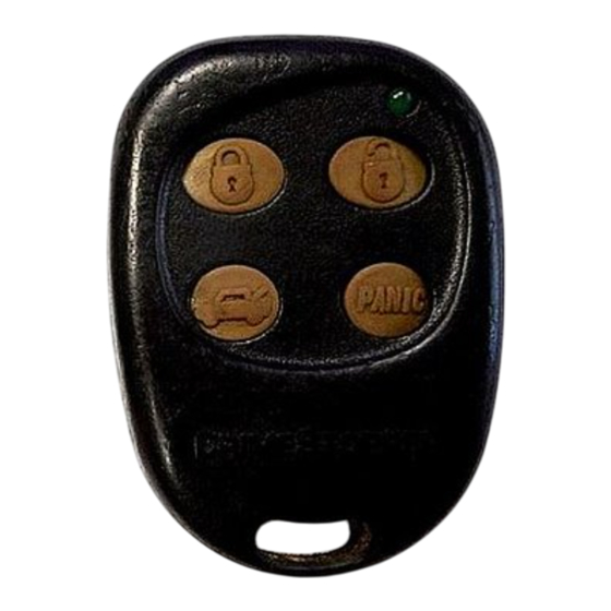
*GREEN LED Blinks once for Bank 1, twice for Bank 2, & 3 times for Bank 3 NOTE: Button #4 on the 1-Way remote reads “Panic”, however on the CS-2013FM system it is only used for Remote Start. ALARM OPERATION... - Page 20 DISARMING: Press Button #1 (Lock Symbol) on the 2-Way remote. For the 1-Way remote Press Button #2 (Unlock Symbol) to disarm. The 2-Way remote will confirm with an “UNLOCK” icon on the LCD display and an audible signal. At the vehicle, the siren will chirp (2) times and the lights will flash (2) times.
-
Page 21: Mode
To arm the system and bypass the shock for just that one time, press button #1 on either remote to arm, then within 10 seconds press Button #1 AGAIN. Siren will chirp 5 times and lights will flash 5 times. ALARM OPERATION VALET MODE: To disable the Alarm functions of the system while still allowing door lock/unlock, turn the ignition ON and press the... - Page 22 PASSIVE ARMING / PASSIVE LOCK MODES: (Programmable) If programmed for passive (Automatic) Arming, the system will Arm itself 30 Seconds after the ignition is turned off and the last door has been closed. The LED will begin flashing rapidly while counting down to Passively Arm. If a door is open or reopened during the countdown, the system will wait (LED solid) for the door or zone to close before arming.
-
Page 23: Remote Engine Start
3. Insert key into the Ignition and turn to the ON position to disarm the alarm. If the key is not turned on within 10 second (i.e. Intruder) then your system will go into a full alarm trigger. PRIOR INTRUSION DIAGNOSTICS (ONE-WAY REMOTE ONLY) This system includes disarm diagnostics, (through the RED LED light), that will help in determining what caused the last trigger of the alarm system. - Page 24 IDLE-DOWN (Continued): Examples of Idle Down uses: • You pull up to a convenience store for a quick stop. The "Idle Down" mode keeps engine running when you exit the vehicle (with keys in hand) and arm the alarm. When you return, unlock/disarm alarm, turn ignition ON and drive away.
- Page 25 SPECIAL 2-WAY LCD FM REMOTE-PAGER FUNCTIONS Clock Setting: 1. Press and hold buttons #2 (Key Symbol) & #3 (Trunk Symbol) together until 2 beeps are heard. 2. Immediately release Buttons #2 & 3. 3. Observe the time display on the LCD screen. Press the #2 button to set the hour and press the #3 button the set minutes. 4.
- Page 26 7. Press button #1. The remote will emit a set tones and the word “OFF” will appear for 5 seconds on the LCD screen.
Need help?
Do you have a question about the CS-2013FM and is the answer not in the manual?
Questions and answers