Table of Contents
Advertisement
Quick Links
40 Class
2-cycle engine
52 Class
4-cycle engine
Or Electric equivalent
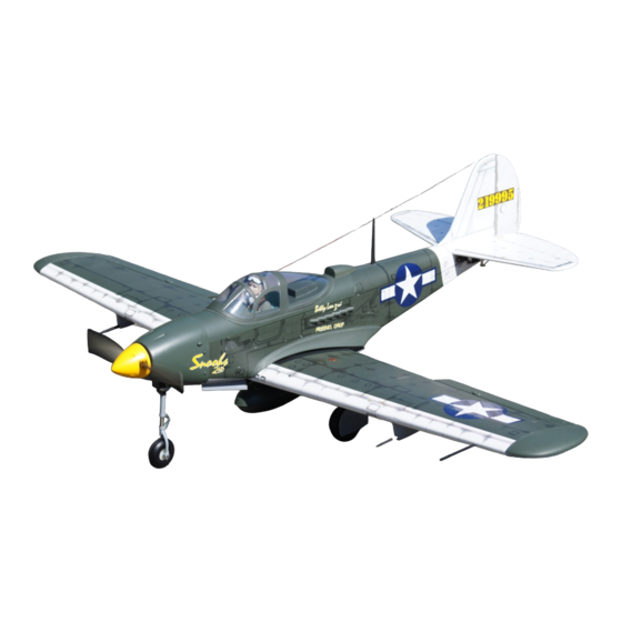
RADIO CONTROLED ALMOST READY-TO-FLY ENGINE POWERED ALL BALSA PLANE
SPECIFICATIONS
Wingspan
Length
Flying weight
Electric Motor
Glow Engine
Radio
Technische Daten
Spannweite
Länge
Fluggewicht
Elektroantrieb
Verbrennerantrieb
Fernsteuerung
WARNING! This radio controlled model is NOT a toy. If modified or flown carelessly it could go out of controll and
cause serious human injury or property damage. Before flying your airplane, ensure the air field is spacious enough.
Always fly it outdoors in safe areas and seek professional advice if you are unexperienced.
ACHTUNG! Dieses ferngesteuerte Modell ist KEIN Spielzeug! Es ist für fortgeschrittene Modellflugpiloten bestimmt,
die ausreichende Erfahrung im Umgang mit derartigen Modellen besitzen Bei unsachgemäßer Verwendung kann
hoher Personen- und/oder Sachschaden entstehen. Fragen Sie in einem Modellbauverein in Ihrer Nähe um
professionelle Unterstützung, wenn Sie Hilfe im Bau und Betrieb benötigen. Der Zusammenbau dieses Modells ist
durch die vielen Abbildungen selbsterklärend und ist für fortgeschrittene, erfahrene Modellbauer bestimmt.
BUILDING INSTRUCTIONS / MONTAGEANLEITUNG
Semi scale model
1580mm
1160mm
2500g
650 Watt
6,5cc 2T / 8,5cc 4-T
7 Channel / 7 Servos
1580mm
1160mm
2500g
650 Watt
6,5cc 2T / 8,5cc 4T
7 Kanal / 7 Servos
Advertisement
Table of Contents

Related Manuals for Nexa P-39 Q/N AIRACOBRA


Summary of Contents for Nexa P-39 Q/N AIRACOBRA
- Page 1 40 Class 2-cycle engine 52 Class 4-cycle engine Or Electric equivalent BUILDING INSTRUCTIONS / MONTAGEANLEITUNG Semi scale model RADIO CONTROLED ALMOST READY-TO-FLY ENGINE POWERED ALL BALSA PLANE SPECIFICATIONS Wingspan 1580mm Length 1160mm Flying weight 2500g Electric Motor 650 Watt Glow Engine 6,5cc 2T / 8,5cc 4-T Radio 7 Channel / 7 Servos...
-
Page 2: Optional Accessories
OPTIONAL ACCESSORIES 10.5x6 for .40 - 2 cycle engine 11x6 for .46 - 2 cycle engine Extension for ailerons, flaps, 11X7 for .52 - 4 cycle engine elevators, rudder servo. 13X8 for Electric motor. Minimum 7 channel radio for airplane with 7 mini servos G-46 HP Motor Silicone tube .Motor control x1 (glow engine) - Page 3 SAFETY NOTES BEFORE ASSEMBLING This model is highly pre-fabricated and can be built in a very short time. However, the work which you have to carry out is important and must be done carefully. The model will only be strong and fly well if you complete your tasks competently - so please work slowly, accurately and check every joints, maybe apply more glue to be safe.
- Page 4 P-39 AIRACOBRA 1- Servo extension cord WING - BOTTOM VIEW Thread the flap and aileron extension cords into the wing with the existing thread. P-39 AIRACOBRA 2- Servo WING - BOTTOM VIEW Adhesive tape -Switch on the radio (trims centered) then mount the ailerons servo horn in neutral position.
- Page 5 P-39 AIRACOBRA 4- Flap & Aileron linkages Threadlocker Do the same way with second wing half. P-39 AIRACOBRA 5- Fixed gear assembling TOP VIEW Using the nylon gear strap Remove the nylon gear Slide the landing gear onto the Reposition the nylon gear as a template, mark the strap and drill a 2mm hole plywood gear mount and push...
-
Page 6: Fixed Gear Installation
P-39 AIRACOBRA 6- Fixed gear installation 2x6mm screw ..4 4mm collar ...2 ..2... - Page 7 P-39 AIRACOBRA 7- Fixed gear installation 50mm...
-
Page 8: Joining The Wing Halves
P-39 AIRACOBRA 8- Joining the wing halves Thin CA Step 8B Perpendicular 6x20mm dowel Step 8A Step 8C Using a pencil, mark the center of the brace. Step 8D Center line Trial fit the wing joiner into one of the wing panels. It should insert smoothly up to the center line marked above. -
Page 9: Engine Mount
P-39 AIRACOBRA 9- Joining the wing halves Nylon wing bolt Rubber band (both the top and bottom) Binder clip Carefully, slide the wing halves together, ensuring that they are accurately aligned. Firmly press the two halves together, allowing the excess epoxy to run out. Clean off the excess epoxy with paper towel and kerosene. IMPORTANT: Please do not clean off the excess epoxy on the wing with strong solvent or pure alcohol, only use kerosene to keep the colour of your model not fade. - Page 10 P-39 AIRACOBRA 11- Engine mount 13/64” - Reposition the engine mounts on to the fire-wall - Remove the engine mounts and drill a 13/64”(5mm) hole and secure them with four 4x25mm screw through the fire-wall at each of the four marks marked. - Attach the four blind-nut to the fire-wall as show 1/8”...
- Page 11 P-39 AIRACOBRA 13- Nose gear Plywood nose gear plate Plastic nose gear mount Insert the nose gear pushrod into the Attach the plastic nose gear mount fuselage with the “Z” bend in front. to the plywood nose gear plate using Secure the plywood nose gear plate four 3x20mm screws and blind nuts.
-
Page 12: Horizontal Stabilizer
P-39 AIRACOBRA 15- Horizontal stabilizer Insert the horizontal stabilizer into the slot on the fuselage, if necessary, use sander to widen the slot to make this easier. Cut away only the covering Using a sharp hobby knife, carefully cut away the covering around of all slots for the horizontal stabilizer and vertical fin installation. -
Page 13: Vertical Stabilizer
P-39 AIRACOBRA 16- Vertical stabilizer B’ Insert the Vertical stabilizer into B=B’ the slot of the fuselage as shown. Step 17B Step 17A Step 17C Step 17D When you are satisfied with the alignment, use a pencil to carefully trace around the left and right of the Vertical stabilizer where it meets the fuselage. - Page 14 P-39 AIRACOBRA 17- Elevator and rudder Push the elevator and its hinges into the hinge slots in the trailing edge of the horizontal stabilizer. When satisfied with the and alignment, hinge the elevator to the horizontal stabilizer using CA glue. Do the same way with the rudder.
-
Page 15: Control Horn
P-39 AIRACOBRA 18- Control horn Plastic control horn ....3 2x12mm screw ....6 1-Depending on the position of the linkage, determine the location of elevator and rudder control horn. 2-Mark the position of the “foot” of the horn on the elevator and rudder. Then, with the drill, make the 2 holes. - Page 16 P-39 AIRACOBRA 20- Cowling 2.5x10mm..4 1.5mm Relieve the cowl to clear the engine head P-39 AIRACOBRA 21- Battery & Fuel tank area Throttle servo hole FUEL TANK OR LI-PO BATTERY AREA Throttle servo hole Nose gear servo hole FUSELAGE - TOP VIEW P-39 AIRACOBRA 22- Canopy hatch 30x4mm nylon bolt...
- Page 17 P-39 AIRACOBRA 23- Aero gun Aerogun Aerogun RIGHT Wing section Aerogun BOTTOM VIEW WRONG Wing section Aerogun P-39 AIRACOBRA 24- Control surface RUDDER 35 mm 35 mm 10mm AILERON 10mm ELEVATOR T ake off 10mm Landing 22mm FLAP IMPORTANT: Flying your model at these throws will provide you with the greatest chance for successful first flights. If,after you have become accustomed to the way the P-39 flies, you would like to change the throws to suit your taste that is fine.
- Page 18 P-39 AIRACOBRA 25- Decal Note: Cut out the stickers and apply them in the proper area. Do not peel the backing paper off all at once. Peel off one corner of the backing and cut off with scissors. Arrange sticker on model and when satisfied adhere the corner without backing. Carefully peel back the rest of the backing while at the same time adhering the rest of the sticker.
- Page 19 P-39 AIRACOBRA 26- Decal THE CENTER OF GRAVITY IS LOCATED 82mm BACK FROM THE LEADING EDGE OF THE WING, AT THE FUSELAGE. BALANCE A PLANE UPSIDE DOWN WITH THE FUEL TANK EMPTY. In order to obtain the CG specified, reposition the receiver and power pack 82mm 1- Mount the wing to the fuselage.
Need help?
Do you have a question about the P-39 Q/N AIRACOBRA and is the answer not in the manual?
Questions and answers