Advertisement
Quick Links
RADIO CONTROL MODEL
R/C FLUGMODEL
SPECIFICATIONS
Wingspan
Length
Flying weight
Electric Motor
Glow Engine
Radio
5 Channel / 5 Servos
Technische Daten
Spannweite
Länge
Fluggewicht
Elektroantrieb
Verbrennerantrieb
Fernsteuerung
WARNING! This radio controlled model is NOT a toy. If modified or flown carelessly it could go out of controll and
cause serious human injury or property damage. Before flying your airplane, ensure the air field is spacious enough.
Always fly it outdoors in safe areas and seek professional advice if you are unexperienced.
ACHTUNG! Dieses ferngesteuerte Modell ist KEIN Spielzeug! Es ist für fortgeschrittene Modellflugpiloten bestimmt,
die ausreichende Erfahrung im Umgang mit derartigen Modellen besitzen Bei unsachgemäßer Verwendung kann
hoher Personen- und/oder Sachschaden entstehen. Fragen Sie in einem Modellbauverein in Ihrer Nähe um
professionelle Unterstützung, wenn Sie Hilfe im Bau und Betrieb benötigen. Der Zusammenbau dieses Modells ist
durch die vielen Abbildungen selbsterklärend und ist für fortgeschrittene, erfahrene Modellbauer bestimmt.
BUILDING INSTRUCTIONS / MONTAGEANLEITUNG
1580mm
1160mm
2700g
700 Watt
7.5cc 2T / 11cc 4-T
1580mm
1160mm
2700g
700 Watt
7.5cc 2T / 11cc 4T
5 Kanal / 5 Servos
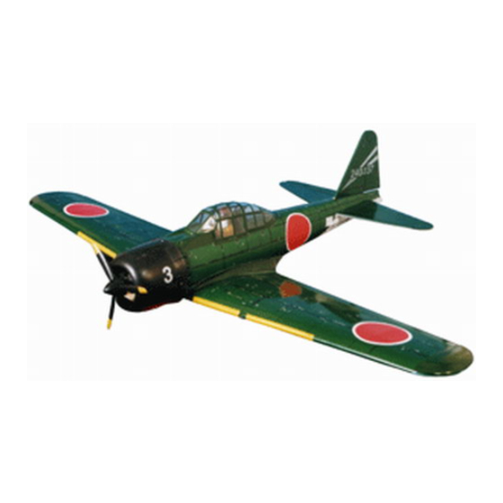
MITSUBISHI A6M5
VQAO14 Gray
VQAO15 Green
VQAO151 White
Advertisement

Related Manuals for Nexa MITSUBISHI A6M5 ZERO


Summary of Contents for Nexa MITSUBISHI A6M5 ZERO
- Page 1 VQAO14 Gray RADIO CONTROL MODEL VQAO15 Green VQAO151 White R/C FLUGMODEL BUILDING INSTRUCTIONS / MONTAGEANLEITUNG SPECIFICATIONS MITSUBISHI A6M5 Wingspan 1580mm Length 1160mm Flying weight 2700g Electric Motor 700 Watt Glow Engine 7.5cc 2T / 11cc 4-T Radio 5 Channel / 5 Servos Technische Daten Spannweite 1580mm...
- Page 2 OPTIONAL ACCESSORIES / BENOTIGTES ZUBEHOR 10.5x6 for .40 - 2 cycle engine Extension for aileron 11x6 for .46 - 2 cycle engine flap and retract servo. 12x6 for .60 - 4 cycle engine 12x7 for .70 - 4 cycle engine 13x8 for Brushless Motor NXA1017-116 ESC 60-70A...
- Page 3 A6M5 ZERO MAIN WING: Extension cord & Servo Using the thread (pre-installed at factory) to slide the aileron and flap extension cord into the wing half. Flap servo extension cord Aileron servo extension cord Electric retract and strut not included OPTIONAL ACCESSORIES: VQAS02 VQARE04...
- Page 4 A6M5 ZERO MAIN WING: Control horn & Linkages Plastic control horn ....2 set Secure the plastic control horn Plastic control horn in place using the thin CA glue.....2 set 2x20mm screw ..4 2 mm connector Flap push-rod 1.2x120mm 2 mm Connector Plastic EZ link ....2...
- Page 5 A6M5 ZERO MAIN WING: Joining the wing halves Draw the center line on the wing joiner 6x20mm dowel. Without using Epoxy yet, trial fit the wing joiner into one of the wing panels. Next, slide the other wing half onto the dihedral brace until the wing panels meet.
- Page 6 A6M5 ZERO MAIN WING: Fixed gear assembly Main landing gear 3x20mm Nylon gear strap Ply gear mount flat Square plastic Gear mount Insert the main landing gear into the slot on the gear mount, if necessary, use sander to widen the slot to make this easier.
- Page 7 A6M5 ZERO MAIN WING: Wheel and wheel cover ABS Wheel well cover Step A Step B Step C Step D Plastic track 2x6mm screw ..4 Step E Plastic landing wheel cover 4mm collar ...2 ..2...
- Page 8 A6M5 ZERO FUSELAGE: Engine mounts installation Attach the engine mount beams onto the fire-wall so the distance between of two engine mount beams is “A”,and B=B’ as show. Secure the engine mount beams onto the fire-wall with litter CA glue (1B) Push left (or right) the magnetic fuel tank hatch and full it out of the fuselage.
- Page 9 A6M5 ZERO FUSELAGE: Engine installation 125mm C=125mm ! Engine thrust on balk head FUSELAGE is already adjust at factory SIDE-VIEW Step A Position the engine to the engine mounts so the distance from the prop hub to the fire-wall is 125mm. Mark the engine mounting plate where the four holes are to be drilled.
- Page 10 A6M5 ZERO FUSELAGE: Electric motor installation Using a aluminum motor mounting plate as a template, mark the plywood motor mounting plate where the four holes are to be drilled. Step A Remove the aluminum motor mounting plate and drill a 1/8”(3mm) hole through the plywood at each of the four marks marked .
-
Page 11: Horizontal Stabilizer
A6M5 ZERO Attach the wing to the fuselage 6x50mm nylon bolt ..2 A6M5 ZERO HORIZONTAL STABILIZER Remove the left and right elevator out of the horizontal stabilizer. If the fit is overly tight, it may be necessary to lightly sand the top edge of the slot. Cut away only the covering both side Cut away only... - Page 12 A6M5 ZERO Determination of installation location Check the alignment of the horizontal stabilizer by measuring from a fixed point along the center line of the fuselage to the leading edge on each side of the horizontal stabilizer. The distance must be equal on both sides .
- Page 13 A6M5 ZERO Glue the horizontal stabilizer to the fuselage Apply thin CA glue into the slot where the fuselage meet the horizontal stabilizer. Apply CA glue both sides. (thin CA) ! Securely glue together. If coming off during fly, you lose control of your air plane. A6M5 ZERO Determination of installation location Carefully, push the vertical fin into the...
- Page 14 A6M5 ZERO Glue the vertical stabilizer to the fuselage Remove the vertical stabilizer from the fuselage. Using s sharp hobby knife, carefully cut away the covering below the lines which were drawn in the previous steep. Do not cut into the woods as this will affect the structural integrity of the stabilizer .
- Page 15 A6M5 ZERO FUSELAGE: Tail gear installation 3x10mm screw ..X 4 2.2mm collar ...1 25mm wheel ...1...
- Page 16 A6M5 ZERO Glue the rudder to the vertical stabilizer Remove the rudder and drill 2mm hole. Place the rudder on the trailing edge of vertical stabilizer as show. Mark the mounting hole position with a pencil. Apply CA glue both sides. (thin CA) Drop a drop of CA glue into the...
- Page 17 A6M5 ZERO Attach the control horns Control horn ....3 2x12mm screw ..6 Rudder push rod line Elevator push rod line Elevator push rod line Elevator control horn flat Elevator control horn flat A6M5 ZERO Attach the tail gear shield...
-
Page 18: Installing The Linkages
A6M5 ZERO Attach the tail gear shield 2x8mm screw ..X 6 Place the ABS tail gear cover on the bottom of fuselage as show and secure it in place using six 2x8mm screw. Attach the ABS tail cone in place and secure it with litter CA glue or screws (screws not included) A6M5 ZERO... - Page 19 A6M5 ZERO Canopy hatch and Cowl installation 4x30mm plastic screw 2.5x10mm screw ..2 ..X 4 A6M5 ZERO Decal E-141 Gray and white version Green version Note: Cut out the stickers and apply them in the proper area. Do not peel the backing paper off all at once. Peel off one corner of the backing and cut off with scissors.
- Page 20 A6M5 ZERO Balance and control throw recommendation THE CENTER OF GRAVITY IS LOCATED 107mm BACK FROM THE LEADING EDGE OF THE WING, AT THE FUSELAGE. BALANCE A PLANE UPSIDE DOWN WITH THE FUEL TANK EMPTY. 107mm 1- Mount the wing to the fuselage. Using a couple of pieces of masking tape, place them on the top side of the wing (107mm) back from the leading edge, at the fuselage sides.
Need help?
Do you have a question about the MITSUBISHI A6M5 ZERO and is the answer not in the manual?
Questions and answers