Advertisement
Quick Links
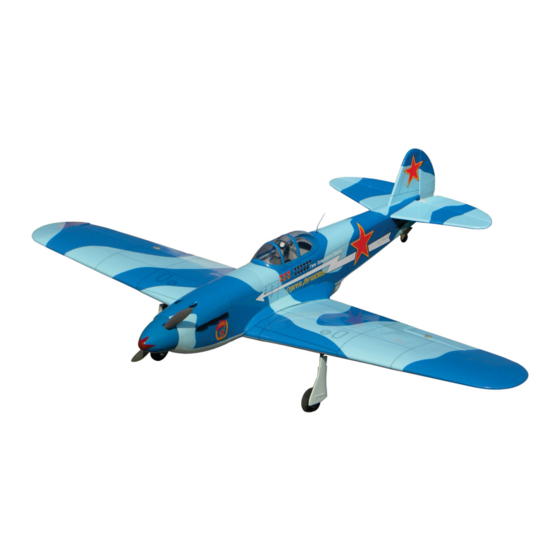
45 Class
2-cycle engine
70 Class
4-cycle engine
Or Electric equivalent
TECHNISCHE DATEN
Spannweiter
Lange
Elektroantrieb
Verbrennerantrieb
Fernsteuerung
WARNING! This radio controlled model is NOT a toy. If modified or flown carelessly it could go out of controll and
cause serious human injury or property damage. Before flying your airplane, ensure the air field is spacious enough.
Always fly it outdoors in safe areas and seek professional advice if you are unexperienced.
ACHTUNG! Dieses ferngesteuerte Modell ist KEIN Spielzeug! Es ist für fortgeschrittene Modellflugpiloten bestimmt,
die ausreichende Erfahrung im Umgang mit derartigen Modellen besitzen Bei unsachgemäßer Verwendung kann
hoher Personen- und/oder Sachschaden entstehen. Fragen Sie in einem Modellbauverein in Ihrer Nähe um
professionelle Unterstützung, wenn Sie Hilfe im Bau und Betrieb benötigen. Der Zusammenbau dieses Modells ist
durch die vielen Abbildungen selbsterklärend und ist für fortgeschrittene, erfahrene Modellbauer bestimmt.
INSTRUCTION MANUAL / Montageanleitung
All balsa, plywood construction and almost ready to fly
1520mm
1237mm
800-900Watt
7.5cc 2-T / 11cc 4-T
6 Kanal / 6-7 Servos
YAK
SPECIFICATIONS
Wingspan
Length
Electric Motor
Glow Engine
Radio
6 Channels / 6-7Servos
59.8 in.
48.7 in.
800-900Watt
.46 2-T / .70 4-T
Advertisement

Subscribe to Our Youtube Channel
Related Manuals for Nexa YAK-9


Summary of Contents for Nexa YAK-9
- Page 1 45 Class 2-cycle engine 70 Class 4-cycle engine Or Electric equivalent INSTRUCTION MANUAL / Montageanleitung All balsa, plywood construction and almost ready to fly SPECIFICATIONS TECHNISCHE DATEN Wingspan 59.8 in. Spannweiter 1520mm Length 48.7 in. Lange 1237mm Electric Motor 800-900Watt Elektroantrieb 800-900Watt Glow Engine...
- Page 2 OPTIONAL ACCESSORIES / BENOTIGTES ZUBEHOR 10.5x6 for .40 - 2 cycle engine Extension for aileron 11x6 for .46 - 2 cycle engine flap and retract servo. 12x6 for .60 - 4 cycle engine 12x7 for .70 - 4 cycle engine 11x8 for Brushless Motor www.motionrc.com ESC:60-65A...
- Page 3 YAK-9 1- MAIN WING: Extension cord & Servo Read through the manual before you begin, so you will have an overall idea of what to do. SAFETY NOTES BEFORE ASSEMBLING This model is highly pre-fabricated and can be built in a very short time. However, the work which you have to carry out is important and must be done carefully.
- Page 4 YAK-9 2- MAIN WING: Control horn & Linkages Plastic control horn ....2 set Secure the plastic control horn Plastic control horn in place using the thin CA glue.....2 set 2x20mm screw ..4 2 mm connector Flap push-rod 1.2x120mm 2 mm...
- Page 5 YAK-9 3- MAIN WING: Joining the wing halves Draw the center line on the wing joiner 6x20mm dowel. Without using Epoxy yet, trial fit the wing joiner into one of the wing panels. Next, slide the other wing half onto the dihedral brace until the wing panels meet.
- Page 6 YAK-9 4- MAIN WING: Fixed gear assembly Main landing gear 3x20mm Nylon gear strap Ply gear mount flat Square plastic Gear mount Insert the main landing gear into the slot on the gear mount, if necessary, use sander to widen the slot to make this easier.
- Page 7 YAK-9 5- MAIN WING: Wheel Wheel well cover Step 5A Attach the plastic wheel well cover in place and secure it with litter CA glue or 2x8mm screws. Step 5B Step 5C 1.5mm Plastic track 2x6mm screw Step 5E ..4 4mm collar ..2...
- Page 8 YAK-9 6- MAIN WING: E-retract & strut Note: Eretract and strut must be purchase separately www.motionrc.com GEAR SWITCH EXTENDED RETRACTED Step 6A Step 6B Fix the adapter in the retract with hexagon socket screws supplied with scale oleo strut. Step 6C Fix the strut on the adapter..
- Page 9 YAK-9 7- MAIN WING: E-retract & strut Step 7A Step 7B Drill appropriately sized holes for the hardware you intend to use (not supplied) then attach the retract in place (we recommend to use self tapping screws 3x15mm). Step 7C Slip the wheel on the axle with the circlip pointing away from the strut...
- Page 10 YAK-9 8- Attach the wing to the fuselage Cut away only the covering 6x40mm nylon bolt ..2 YAK-9 9- Air scoop Thin CA Apply the plastic air scoop (part B) in place and secure with CA glue. Using the ABS air scoop (part A) as a template, trace around the outside edge of the ABS air-scoop and then remove it.
- Page 11 YAK-9 10- Air scoop continued Be cautious not to cut into the wood, this will Using a sharp hobby knife, cut away the covering weaken the structure. inside the lines. Not to cut into the wood. Thin CA YAK-9 11- Horizontal stabilizer...
- Page 12 YAK-9 12- Horizontal stabilizer continued A’ B’ A=A’ and B=B’ Check the alignment of the horizontal stabilizer When you are satisfied with the alignment (A=A’ and B=B’), use a pencil to trace around the top and bottom of the stabilizer where it meets the fuselage.
- Page 13 YAK-9 12- Vertical stabilizer Note: The hinges are glued to the rudder only. Check the alignment of the vertical stabilizer. When you are satisfied with the alignment, use a pencil to trace around the right and left of the stabilizer where it meets the fuselage.
- Page 14 YAK-9 13- Vertical stabilizer Thin CA Securely glue together. If coming off during flight, you lose control of your air plane. Thin CA Control horn ....3 2x12mm screw ..6 Note: Push the elevator push-rod into the fuselage before attach the elevator control horn.
- Page 15 YAK-9 14- Tail wheel 2x8mm screw 2x3mm screw 2mm I.D collar ....2 ....2 2x18mm screw 1- Insert the tail wheel pushrod into the hole on the tail gear control horn (as show). Tail landing gear ....4 2- Install the tail wheel control horn in place.
- Page 16 YAK-9 16- Glow engine continued 4x25mm hex bolt ..4 Blind-nut ....4 4mm washer ....4 Attach the four blind-nuts to the fire-wall as show, then reposition the engine mounts on to the fire-wall and secure them with four 4x25mm hex bolts.
- Page 17 YAK-9 17- Electric motor Step 17B ! Align the mark on wooden motor mounting plate with the mark on the fire-wall. Using a aluminum motor mounting plate as a template, mark the plywood motor mounting plate where the four holes are to be drilled.
- Page 18 YAK-9 18- Fuel tank To muffler Filler tube Rubber stopper To engine 3x35mm screw After confirming the direction . Insert this assembly, clunk end first, into the fuel tank and tighten and screw the fuel tankcap on firmly. Ensure that the fuel tank clunk does not touch the rear of the fuel tank.
- Page 19 YAK-9 20- Servo NOTE: Place of the servos may be change depend of engine (Four-stoke or two-stroke engine) YAK-9 21- Linkages Elevator push rod Tail wheel push rod Elevator push rod Rudder push rod Connector Connector Rudder servo Elevator servo...
- Page 20 IMPORTANT: Flying your model at these throws will provide you with the greatest chance for successful first flights. If,after you have become accustomed to the way the Yak-9 flies, you would like to change the throws to suit your taste that is fine.
Need help?
Do you have a question about the YAK-9 and is the answer not in the manual?
Questions and answers