Advertisement
60 Class
2-cycle engine
90 Class
4-cycle engine
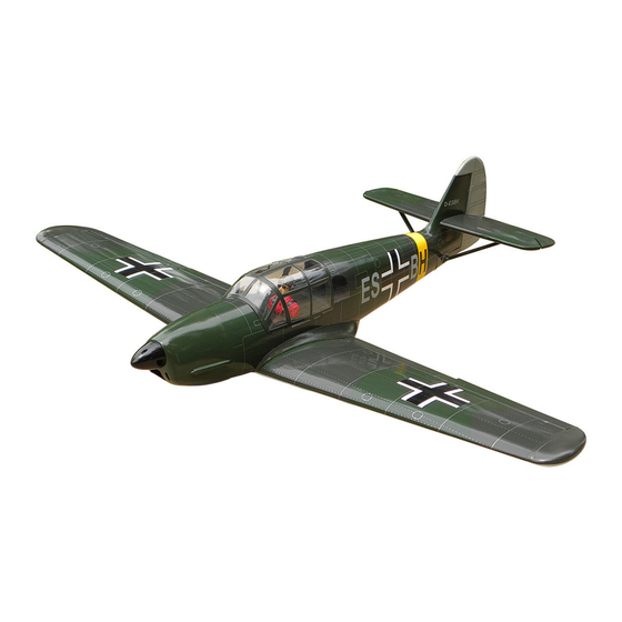
SPECIFICATIONS
Wingspan
Length
Flying weight
Electric Motor
Glow Engine
Radio
Technische Daten
Spannweite
Länge
Fluggewicht
Elektroantrieb
Verbrennerantrieb
Fernsteuerung
WARNING! This radio controlled model is NOT a toy. If modified or flown carelessly it could go out of controll and
cause serious human injury or property damage. Before flying your airplane, ensure the air field is spacious enough.
Always fly it outdoors in safe areas and seek professional advice if you are unexperienced.
ACHTUNG! Dieses ferngesteuerte Modell ist KEIN Spielzeug! Es ist für fortgeschrittene Modellflugpiloten bestimmt,
die ausreichende Erfahrung im Umgang mit derartigen Modellen besitzen Bei unsachgemäßer Verwendung kann
hoher Personen- und/oder Sachschaden entstehen. Fragen Sie in einem Modellbauverein in Ihrer Nähe um
professionelle Unterstützung, wenn Sie Hilfe im Bau und Betrieb benötigen. Der Zusammenbau dieses Modells ist
durch die vielen Abbildungen selbsterklärend und ist für fortgeschrittene, erfahrene Modellbauer bestimmt.
BUILDING INSTRUCTIONS / MONTAGEANLEITUNG
1625mm
1300mm
2900g
800 Watt (BOOST 60)
10cc 2T / 15cc 4-T
6 Channel / 7 Servos
1625mm
1300mm
2900g
800 Watt (BOOST 60)
10cc 2T / 15cc 4T
6 Kanal / 7 Servos
"Taifun"
Advertisement
Table of Contents

Related Manuals for Nexa MESSERSCHMITT ME-108 Taifun


Summary of Contents for Nexa MESSERSCHMITT ME-108 Taifun
- Page 1 60 Class 2-cycle engine “Taifun” 90 Class 4-cycle engine BUILDING INSTRUCTIONS / MONTAGEANLEITUNG SPECIFICATIONS Wingspan 1625mm Length 1300mm Flying weight 2900g Electric Motor 800 Watt (BOOST 60) Glow Engine 10cc 2T / 15cc 4-T Radio 6 Channel / 7 Servos Technische Daten Spannweite 1625mm...
- Page 2 REQUIRED FOR OPERATION (Purchase separately) BENOTIGTE KOMPONENTEN FUR DEN ABFLUG (Nicht enthalten) 12x6 for .60 - 4 cycle engine 13x7 for .90 - 4 cycle engine 14X8 for Quantum 4120/07 BOOTS 60 Phoenix-60 Brushless Motor Control or equivalent. Extension for aileron servo, retract servo.
-
Page 3: Joining The Wing
1- Joining the wing ME-108 TAIFUN adhesive tape the thread is used to hold the extension cord. 6x20mm wooden dowel Draw the center line on the wing joiner Before gluing: - Draw the center line on the wing joiner. - Trial fit each part before gluing . Be certain that there are no gaps. If the parts will join, but with a gaps, sand or trim the parts a little at a time until the parts meet exactly with no gaps. - Page 4 2- Joining the wing ME-108 TAIFUN Nylon wing bolt Rubber band (both the top and bottom) Binder clip 30 min.Epoxy IMPORTANT: Please do not clean off the excess epoxy on the wing with strong solvent or pure alcohol, only use kerosene to keep the colour of your model not fade. 3- Fixed gear assembly ME-108 TAIFUN Main landing gear...
-
Page 5: Fixed Gear Installation
4- Fixed gear installation ME-108 TAIFUN STEP 1 3x12mm screw ..4 ..2 STEP 2... - Page 6 5- Wheel ME-108 TAIFUN STEP 3 STEP 4 Plastic strap ..1 4mm collar ..1 2x6mm screw ..4 STEP 5...
- Page 7 6- Flap and aileron servo mounts ME-108 TAIFUN Using the thread (pre-installed at factory) to slide the aileron and flap extension cord into the wing. Flap extension cord FLAP & AILERON SERVO HATCH BOTTOM VIEW Aileron extension cord Hard wood servo mount ! Securely glue together.
- Page 8 7- Flap and aileron linkages ME-108 TAIFUN Connector (included) 2x175mm rod with clevis ...2 Control horn ......4 Set Connector 2mm ......2...
-
Page 9: Horizontal Stabilizer
8- Horizontal stabilizer ME-108 TAIFUN Cut away only the covering both the right and left side NOTE: You may need to open up the slots with the thin sander so that the horizontal stabilizer is not too difficult to push .in B’... - Page 10 9- Horizontal stabilizer ME-108 TAIFUN Apply thin CA glue both sides Install the horizontal stabilizer onto the fuselage and adjust the alignment as described before. Note: it is important to ensure that the horizontal stabilizer is also level in regards to the fuselage. Apply the thin CA along the area where the covering was removed in the previous step and to the fuselage where the horizontal stabilizer mounts .
- Page 11 10- Rudder ME-108 TAIFUN Plastic control horn ...3 set Securely glue together. If coming off during flight, you lose control of your air plane. 11- Tail wheel mount ME-108 TAIFUN 3x12mm screw ..4 BOTTOM VIEW UNTERSICHT 12- Tail wheel ME-108 TAIFUN BOTTOM VIEW Tail wheel control arm UNTERSICHT...
-
Page 12: Glow Engine
13- Tail brace ME-108 TAIFUN ABS Shield 1-Position the tail brace in place (1). Using the pencil mark the location of the two brace holes as show (2). 2-Remove the tail brace and drill two 1/16” (1.5mm) as show (3). 1/16”... - Page 13 15- Glow engine ME-108 TAIFUN Insert the blind-nut onto each of the four holes make above. Reposition the engine mount beams on to the fire-wall and secure them with four 4x25mm screw. 4x25mm screw - washer ....4 Blind-nut ....4 Fire-wall 128mm Position the engine to the engine mounts so the distance from the prop hub to the fire-wall is 128mm.
- Page 14 16- Glow engine ME-108 TAIFUN Reposition the engine on the engine mount beams, aligning it with the holes. Secure the engine to the engine mount using four 3x25mm screws Note: Apply Silicon sealer to each of the 3x25mm screw and nut. 3x25mm screw ..4 Washer...
-
Page 15: Electric Motor
17- Electric motor ME-108 TAIFUN Using the hobby knife, cut off the 63mm firewall along the stripes. 52mm FIREWALL - FRONT VIEW This cutout allows the Lipo-battery to move to the front as much as possible. Remove the aluminum motor mounting plate and drill a 1/8”(3mm) hole through 3mm bolt / nut...4 the plywood at each of the four marks... - Page 16 18- Electric motor ME-108 TAIFUN Using a wooden motor mounting plate as a template, mark the fire-wall where the four holes are to be drilled. ! Align the mark on wooden motor mounting plate with the mark on the fire-wall. Mark the firewall here Mark the firewall here Remove the wooden motor mounting plate and drill a 5mm...
- Page 17 19- Electric motor ME-108 TAIFUN SIDE-VIEW / Seitenansicht 128mm FUSELAGE B’ B=B’ ! Motor thrust on balk head is already adjust at factory 1.5mm 1.5mm 3/32x25/64” self tapping screw 2.5x10mm ....5...
- Page 18 20- Servo ME-108 TAIFUN Tail wheel pushrod Rudder servo FUSELAGE BOTTOM-VIEW UNTERSICHT Rudder pushrod FUEL Servo mount TANK Elev. Pushrod (x2) Throttle pushrod Elevator servo Throttle servo Elevator pushrod 3mm set Screw 3mm set Screw Elevator pushrod throttle pushrod or rudder pusshrod D=.050”(1.2mm) D=5/64”(2mm) Tail wheel pushrod...
-
Page 19: Wing Installation
22- ABS Shield ME-108 TAIFUN BOTTOM-VIEW UNTERSICHT ABS Shield 1.5mm ABS Shield ABS pushrod exit guider ABS Shield 2x10mm screw ..6 Slide the two ABS in place and secure them with CA glue. 23- Wing installation ME-108 TAIFUN BOTTOM-VIEW UNTERSICHT 6x50mm Nylon bolt 6x50mm Nylon bolt...
Need help?
Do you have a question about the MESSERSCHMITT ME-108 Taifun and is the answer not in the manual?
Questions and answers