Advertisement
Available languages
Available languages
Quick Links
INSTRUCTION MANUAL
MONTAGEANLEITUNG
Radio control model / R/C Flugmodel
TECHNISCHE DATEN
Spannweiter
Lange
Elektroantrieb
870 Watt (PULSAR 60)
Verbrennerantrieb
7.5cc 2-T / 11cc 4-T
Fernsteuerung
WARNING! This radio controlled model is NOT a toy. If modified or flown carelessly it could go out of controll and
cause serious human injury or property damage. Before flying your airplane, ensure the air field is spacious enough.
Always fly it outdoors in safe areas and seek professional advice if you are unexperienced.
ACHTUNG! Dieses ferngesteuerte Modell ist KEIN Spielzeug! Es ist für fortgeschrittene Modellflugpiloten bestimmt,
die ausreichende Erfahrung im Umgang mit derartigen Modellen besitzen Bei unsachgemäßer Verwendung kann
hoher Personen- und/oder Sachschaden entstehen. Fragen Sie in einem Modellbauverein in Ihrer Nähe um
professionelle Unterstützung, wenn Sie Hilfe im Bau und Betrieb benötigen. Der Zusammenbau dieses Modells ist
durch die vielen Abbildungen selbsterklärend und ist für fortgeschrittene, erfahrene Modellbauer bestimmt.
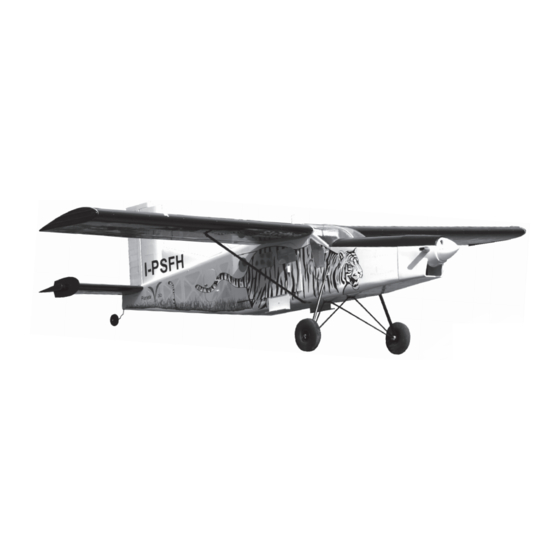
PILATUS PORTER
PC-6
SPECIFICATIONS
1580mm
1160mm
5 Kanal / 5 Servos
Wingspan
Length
Electric Motor
870 Watt (PULSAR 60)
Glow Engine
Radio
5 Channel / 5 Servos
46 Class
(2T engine)
52 Class
(4T engine)
Or Electric equivalent
1580mm
1160mm
.46 2-T / .70 4-T
Advertisement

Related Manuals for Nexa PILATUS PORTER PC-6


Summary of Contents for Nexa PILATUS PORTER PC-6
- Page 1 INSTRUCTION MANUAL MONTAGEANLEITUNG Radio control model / R/C Flugmodel PILATUS PORTER PC-6 46 Class (2T engine) 52 Class (4T engine) Or Electric equivalent SPECIFICATIONS TECHNISCHE DATEN Wingspan 1580mm Spannweiter 1580mm Length 1160mm Lange 1160mm Electric Motor 870 Watt (PULSAR 60) Elektroantrieb 870 Watt (PULSAR 60) Glow Engine...
- Page 2 REQUIRED FOR OPERATION (Purchase separately) BENOTIGTE KOMPONENTEN (Nicht im Lieferumfang enthalten) Propeller 11x8 for electric motor / 11x6 for glow engine Luftschraube 11x8 fur Elektromotor / 11x6 fur Verbrennungsmotor Extension cord Servoverlangerungskabel Brushless Motor Minimum 5 channel radio PICHLER BOOST 40 for airplane Brushless ESC Minimum 5 Kanal...
- Page 3 Note: The hole for the Linkage stopper installation is pre-drilled at factory B: 8-10mm Gestängeanschluss Thin CA 1.2mm O Alenk-Gestange 2x20mm screw 6mm wooden dowel Thin CA Thin CA 6mm wooden dowel x4 Plastic control horn ......2 2x20mm screw Cut here for standard servo ....4 Linkage Stopper set .....2...
-
Page 4: Front View
Note: The Pilot seater can move for the engine-mount 3x20mm screw 4x25mm screw and servos installation is easily..4 ..4 Blind-nut 3mm nut .....4 .....4 3mm washer 4mm washer .....4 .....4 18mm wooden washer..4 Align the mark on both mounts with the center mark on the fire-wall Motorträger 18mm wooden... - Page 5 FRONT-VIEW Plywood motor mounting plate Vorderansicht Sperrholztrager Platten - Using a plywood motor mounting plate as a template, mark the fire wall where the four holes are to be drilled (1). - Remove the plywood motor mounting plate and drill a 13/64”(5mm) hole through the fire-wall at each of the four marks marked (2).
- Page 6 SIDE-VIEW / Seitenansicht B=B’ B’ Firewall 107~110mm Motorspant TOP-VIEW / Draufsicht A=A’ A’ Note the side thrust for motor! Sturz und Zug beachten!
- Page 7 3x8mm screw Blechschraube ....4 2 mm Falls ein Verbrennungsmotor eingebaut wird mu die Motorhaube entsprechend dem Zylinder ausgeschnitten werden. Trim the cowling so it will match your engine 2 mm 3mm set Screw Receiver and battery Madenschraube M3 Akku & Empfänger in Schaum lagern Pushrod Linkage Stopper set...
- Page 8 Collar Stellring 3mm set screw Stopper (metal) Madenschraube M3 Nylon strap Kunststoffstreifen Fahrwerksdraht 2.5mm landing Collar 3x12mm screw gear Note: All holes on the bottom of the fuselage are pre-drilled at Aluminum tube factory. 4mm Main landing gear Hauptfahrwerk Stopper (metal) 3x12mm screw ....2 ......12...
-
Page 9: Side View
FUSELAGE - REAR - BOTTOM VIEW 3x15mm screw ..4 ..4 SIDE VIEW BOTTOM FUSELAGE - TOP-VIEW AUFSICHT Cut away only the film on the bottom of the horizontal stabilizer Bespannfolie an den Klebestellen vorsichtig entfernen. WARNING! Securely glue together. * WARNING: When removing any covering If coming off during flights, you lose from the airframe, please ensure that you control of your airplane which leads... - Page 10 Plastic control horn and back plate ..2 2x12mm screw ...4 2x12mm screw 2 mm 2x12mm screw Rudder servo Seitenruder servo Elevator servo Hohenruder servo 2x12mm screw / schraube FUSELAGE - REAR - BOTTOM VIEW / UNTERSICHT ....4 Collar / Gewindestift ....1 Spornrad 30mm...
- Page 11 Thin CA A’ 1- Slide the aluminum tube throughout the fuselage as shown. 2- Secure the aluminum tube in place with thin CA glue, ensuring that the aluminum tube is accurately aligned : A=A’ (very important) Carefully slide the wing halves to the fuselage, ensuring that they are accurately aligned, Firmly press the two halves together.
- Page 12 Secure the wing in place using 3x15mm screw. Note: all holes (2 holes) on the surface of the top 5/64” of the wing are pre-drilled at factory. 2.mm drill bit 3mm aluminum tube Aluminum tube inside 3x15mm screw 3x3mm set screw Linkage Stopper set .....4 Note: All holes for the wing brace...
- Page 13 Cut away only Antenna (plastic) the covering Sticker Sticker WHITE SCHEME VQA037W VQA037Y / VQA037W / VQA0371 Sticker BIRD VERSION VQA0371 Sticker VQA0371 Note: Cut out the stickers and apply them in the proper area. Do not peel the backing paper off all at once. Peel off one corner of the backing and cut off with scissors.
- Page 14 SWISS VERSION VQA0362 Sticker ALP VERSION VQA0374 Sticker TURBOLENZA Sticker Sticker...
- Page 15 Aileron 10mm 10mm Querruderausschlag 20mm Rudder Elevator 10mm 20mm Seitenruderausschlag 10mm Hohenruderausschlag Do not try to fly an out-of balance model! Uberprufen Sie vor dem Flug den Schwerpunkt. 70 ~ 75mm IN CASE OF FLOATING USING Rear floats mounting is pre-assembled Floats mounting (plywood) Note: The landing gear for floating not included This part must be purchased separately...
Need help?
Do you have a question about the PILATUS PORTER PC-6 and is the answer not in the manual?
Questions and answers