Table of Contents
Advertisement
Quick Links
Instruction manual / Montageanleitung
SPECIFICATIONS
Wingspan:.........................2060mm (81.1in)
Length:................................1450mm (57 in)
Electric Motor:.....................See next pager
Gas Engine:................................. 26-30cc
RTF Weight: 7Kg / 15.5lbs (Will vary with
Equipment Used).
Radio:...............8-9 Channel / 10-11 Servos
Function: Ailerons-Elevator-Rudder-Throttle
Flaps-Optional Retractable Landing Gear.
WARNING! This radio controlled model is NOT a toy. If modified or flown carelessly it could go out of controll and
cause serious human injury or property damage. Before flying your airplane, ensure the air field is spacious enough.
Always fly it outdoors in safe areas and seek professional advice if you are unexperienced.
ACHTUNG! Dieses ferngesteuerte Modell ist KEIN Spielzeug! Es ist für fortgeschrittene Modellflugpiloten bestimmt,
die ausreichende Erfahrung im Umgang mit derartigen Modellen besitzen. Bei unsachgemässer Verwendung kann
hoher Personen- und/oder Sachschaden entstehen. Fragen Sie in einem Modellbauverein in Ihrer Nähe um
professionelle Unterstätzung, wenn Sie Hilfe im Bau und Betrieb benötigen. Der Zusammenbau dieses Modells ist
durch die vielen Abbildungen selbsterklärend und ist für fortgeschrittene, erfahrene Modellbauer bestimmt.
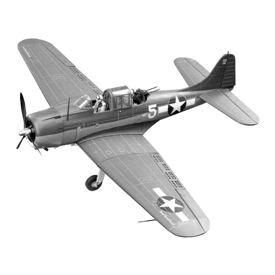
Radio control model / Flugmodel
U.S NAVY DIVE BOMBER
ALL BALSA, PLYWOOD CONSTRUCTION AND ALMOST READY TO FLY
TECHNISCHE DATEN
Spannweite:...................................2060mm
Lange:............................................1450mm
Elektroantrieb.............(siehe nächste Seite)
Verbrennerantrieb:..........................26-30cc
Fluggewicht:..........................................7Kg
Fernsteuerung......8-9 Kanal / 10-11 Servos
Advertisement
Table of Contents

Subscribe to Our Youtube Channel
Related Manuals for Nexa U.S NAVY DIVE BOMBER SBD-5 DAUNTLESS


Summary of Contents for Nexa U.S NAVY DIVE BOMBER SBD-5 DAUNTLESS
- Page 1 Radio control model / Flugmodel U.S NAVY DIVE BOMBER ALL BALSA, PLYWOOD CONSTRUCTION AND ALMOST READY TO FLY Instruction manual / Montageanleitung TECHNISCHE DATEN SPECIFICATIONS Wingspan:......2060mm (81.1in) Spannweite:........2060mm Length:........1450mm (57 in) Lange:..........1450mm Electric Motor:.....See next pager Elektroantrieb.....(siehe nächste Seite) Gas Engine:......... 26-30cc Verbrennerantrieb:......26-30cc RTF Weight: 7Kg / 15.5lbs (Will vary with Fluggewicht:..........7Kg...
- Page 2 REQUIRED FOR OPERATION (Purchase separately) Spinner hub Extension cord for aileron servos: 80cm(x2) Extension cord for flap and brake servos: 50cm(x4) Extension cord for retract servos: 30cm(x2) Extension cord for Rx battery pack: 30cm(x1) Extension cord for Elevator servos: 80cm(x2) Minimum 8-9 channels radio with 8 mini servos and 3 standard Servo (for GP).
- Page 3 1- Center Wing GEAR SWITCH Push the wooden dowel to the hole on the rib as show. Ensure that the dowel is rectangular with the rib. Secure it in place using the thin CA glue. Connect all electric retract to the receiver. Thin CA Move the Struts out Move the Struts out...
- Page 4 2- Center Wing: Flap servo Flap push rod (one end to servo) Flap control horn Connector ....1 2x170mm.......1...
-
Page 5: Joining The Wing
3- Gear door Note: Do not glue the wooden gear door mounts to the struts at this time. 4- Joining the wing Connect the electric retract with the radio to check the position of the wheel when the electric retract in retracted position. - Page 6 5- Right / Left wing halves: Servo Aileron servo hatch Brake servo Flap servo Connector ....6 Flap and brake push rod (one end to servo) 2x170mm.......4 Flap and brake control horn Aileron servo Hatch WING BOTTOM AIL. Servo mount Control horn ....2 2x30mm ..4...
- Page 7 6- Joining the wing ..2 5x20mm screws Apply the 30 min. Epoxy to the dowels, aluminum tube, the one end of the center wing and right wing. Note: connected the servo wires at this time. 4x20mm Carefully slide the center wing and right wing together, ensuring that they are accurately aligned.
- Page 8 Fuselage - front view 7- Engine A1 A2 Full the magnetic canopy hatch out of the fuselage. B1=B2 A1=A2 Mark the plywood where the four holes are to be drilled. Step 1 Step 2 Step 3 Step 4 The long of the aluminum tubes are the same. Note: The aluminum tube not include.
-
Page 9: Electric Motor
8- Engine Continued Please Note: This plane was design to use for 30cc gasoline-2 stroke engine or 40cc-4 stroke engine. Incase you want to use bigger engine, please reinforce the firewall and other connection by Epoxy 9- Fuel tank Filler tube Rubber stopper Air tube... -
Page 10: Horizontal Stabilizer
11- Horizontal stabilizer * WARNING: When removing any covering from the airframe, please ensure that you secure the cut edge with CA or similar cement. This will ensure the covering remain tight. Step 11A C’ Cut away only the covering* If the fit is overly tight, it may be necessary to lightly sand the hole on the fuselage. - Page 11 Again, trial fit the horizontal stabilizer in place on the fuselage and 12- Horizontal stabilizer Continued adjust the alignment as described in Step 11A. Secure the stabilizer in place using the thin CA glue (Step 12A). 15 min. Epoxy Thin CA Step 12A Step 12B Add a thin layer of 15 minutes Epoxy...
- Page 12 14-Elevator Continued Step 14B Elevator Safety Step 14A Toothpick (x 12pcs) Not include 1.5mm 1.5mm 1.5mm 1.5mm 1.5mm 1.5mm Thin CA glue Step 14C Cut the excess toothpick and secure it HORIZONTAL STABILIZER in place using little Thin CA glue. Toothpick 15- Rudder Rudder torque rod bearing...
-
Page 13: Tail Wheel
16 Tail wheel 1- Slide the wire, straight end first, into the push rod tube 2- Insert the Z-bend into the hole on the tail wheel control arm. 3- Place the tail wheel control arm to the center of the tail wheel mount. - Page 14 17- Guns...
- Page 15 18- Bomb...
- Page 16 19- Bomb 20- Bomb 11mm diameter aluminum tube 2mm diameter steel wire Silicon tube...
- Page 17 21- Bomb Nylon control horn 2x6mm screw 1.5mm...
- Page 18 22- Hook 8mm diameter aluminum tube Wing - bottom view BLACK NYLON TUBE 23- Decor Black nylon wire Wing surface Do the same way with other side Black nylon wire WING- TOP VIEW...
- Page 19 24- Servo Connector ....4 Magnetic Pilot sitter Switch hole Remove before installing servo FUSELAGE TOP-VIEW Elevator push rod Tail wheel push rod Rudder push rod Elevator push rod 25- Guns - Antenna...
- Page 20 26- Rear Canopy 27- Magnetic canopy hatch / Step Step Step Step Cut the opening Cut the opening...
- Page 21 28- Cowling Note: secure the plastic dummy engine using 5 min.Epoxy. Plastic dummy engine 1.5mm 1.5mm Secure the cowling in place using 2.5x12mm screws. 2.5x12mm screw ..6 28- Balance Note: Adjust the location of the battery pack to achieve this C.G location. (128 ~ 133mm) DO NOT try to fly an out-of balance model! Wing center section...
-
Page 22: Control Surface
29- Control surface (20mm) (20mm) AILERON STROKE (15mm) (15mm) ELEVATOR STROKE (40mm) (25mm) CENTER FLAP STROKE (25mm) RUDDER STROKE RIGHT&LEFT BRAKE STROKE (40mm) (40mm) RIGHT&LEFT FLAP STROKE Adjust the travel of the control surfaces to achieve the values stated in the diagrams. These value will be suitable for average flight requirements.
Need help?
Do you have a question about the U.S NAVY DIVE BOMBER SBD-5 DAUNTLESS and is the answer not in the manual?
Questions and answers