Table of Contents
Advertisement
Quick Links
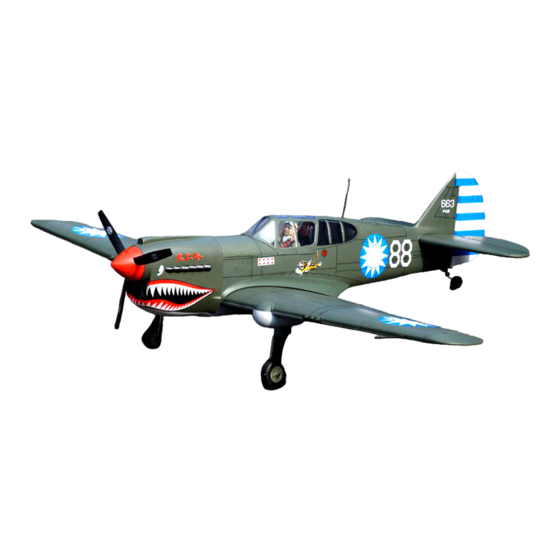
INSTRUCTION MANUAL / MONTAGEANLEITUNG
TECHNISCHE DATEN
Spannweiter
Lange
Elektroantrieb
900 Watt Brushless Motor
Verbrennerantrieb
Fernsteuerung
WARNING! This radio controlled model is NOT a toy. If modified or flown carelessly it could go out of controll and
cause serious human injury or property damage. Before flying your airplane, ensure the air field is spacious enough.
Always fly it outdoors in safe areas and seek professional advice if you are unexperienced.
ACHTUNG! Dieses ferngesteuerte Modell ist KEIN Spielzeug! Es ist für fortgeschrittene Modellflugpiloten bestimmt,
die ausreichende Erfahrung im Umgang mit derartigen Modellen besitzen Bei unsachgemäßer Verwendung kann
hoher Personen- und/oder Sachschaden entstehen. Fragen Sie in einem Modellbauverein in Ihrer Nähe um
professionelle Unterstützung, wenn Sie Hilfe im Bau und Betrieb benötigen. Der Zusammenbau dieses Modells ist
durch die vielen Abbildungen selbsterklärend und ist für fortgeschrittene, erfahrene Modellbauer bestimmt.
RADIO CONTROL MODEL
1570mm
1360mm
10cc 2-T / 15cc 4-T
6 Kanal / 7 Servos
SPECIFICATIONS
Wingspan
Length
Electric Motor
900 Watt Brushless Motor
Glow Engine
Radio
6 Channel / 7 Servos
1570mm
1360mm
.60 2-T / .90 4-T
Advertisement
Table of Contents

Subscribe to Our Youtube Channel
Related Manuals for Nexa CURTISS P-40


Summary of Contents for Nexa CURTISS P-40
- Page 1 RADIO CONTROL MODEL INSTRUCTION MANUAL / MONTAGEANLEITUNG SPECIFICATIONS TECHNISCHE DATEN Wingspan 1570mm Spannweiter 1570mm Length 1360mm Lange 1360mm Electric Motor 900 Watt Brushless Motor Elektroantrieb 900 Watt Brushless Motor Glow Engine .60 2-T / .90 4-T Verbrennerantrieb 10cc 2-T / 15cc 4-T Radio 6 Channel / 7 Servos Fernsteuerung...
- Page 2 REQUIRED FOR OPERATION (Purchase separately) BENOTIGTE KOMPONENTEN FUR DEN ABFLUG (Nicht enthalten) 12x6 for .60 - 2 cycle engine 13x7 for .90 - 4 cycle engine Extension for aileron 14X8 for Electric Motor Flap and retract servo. Minimum 6 channel radio Brushless Motor for airplane with 7 servos .60 - 2 cycle...
- Page 3 1-Flap and Aileron servo You can chose to cut either hole (cut only the covering), This hole will allow the flap push-rod through when installing the flap push-rod. Using a hobby knife, remove the covering from over the pre-cut servo arm exit hole on the aileron servo hatch.
- Page 4 2-Flap and Aileron linkages Pre-cut at factory Pushrod exit hole WING BOTTOM Flap servo Hatch FLAP ....2 Servo mount Connector ....2 set 2x175mm rod / clevis ..4 Silicon sealer...
-
Page 5: Plastic Shield Installation
3-Plastic shield installation Note: R for Right wing panel 2x10mm screw ..20 4-Joining the wing 1-Using a pencil, mark the center of brace. Adhesive tape WING TOP-VIEW 2- Trial fit the wing joiner into one of the wing panels. It should insert smoothly up to the center line marked above. 3- Slide the other wing half onto the dihedral brace until the wing panel meet. - Page 6 5-Joning the wing Nylon wing bolt Rubber band (both the top and bottom) Binder clip 6X50mm nylon bolt 6X50mm nylon bolt 6X50mm nylon bolt ..2 Carefully slide the wing halves together, ensuring that they are accurately aligned. Firmly press the two halves together, allowing the excess epoxy to run out. Clear off the excess epoxy. IMPORTANT: Please do not clean off the excess epoxy on the wing with strong solvent or pure alcohol, only use kerosene to keep the colour of your model not fade.
-
Page 7: Horizontal Stabilizer
6- Horizontal stabilizer Trial fit the horizontal stabilizer in place. Check the alignment of the horizontal stabilizer. If the parts will join, but with a gaps, sand the stabilizer slot on the fuselage a little at a time until the parts meet exactly with no gaps. - Page 8 7- Horizontal stabilizer Thin CA glue Install the horizontal stabilizer into the fuselage and adust the alignment as described in steep When you are satisfied with the alignment, with the thin CA glue around the top and bottom of the stabilizer where it meets the fuselage.
-
Page 9: Side View
9- Tail gear 5/64”(2mm) collar 3x12mm screw Tail gear mount 1-Place the tail gear mount on the bottom 1/8x15/32” Tail gear horn of the fuselage as show, mark the (3x12mm) screw mounting hole positions with a pencil....2 2-Remove the tail gear mount from the Tail gear horn fuselage, Drill the two mounting holes as marked. -
Page 10: Electric Motor
11- Fuel tank & cowl To muffler 2.5x10mm..4 Filler tube Rubber stopper Fuel tube Stopper To engine After confirming the direction, insert this assembly, clunk end first, into the fuel tank and tighten and screw the fuel tank cap on firmly. SIDE VIEW 12- Electric motor Firewall... - Page 11 14- Linkages Connector ..3 Connector Connector Rudder Elevator pushrod ..1 pushrod Rudder servo Elevator servo Fuel tank FUSELAGE - BOTTOM VIEW UNTERSICHT 15- ABS Shield FUSELAGE - BOTTOM VIEW UNTERSICHT Cut away only the covering 1-Using the ABS shield as a template, trace around the outside edge of the ABS shield, and then remove it.
- Page 12 16- Decal CHINESE AIR-FORCE (AVG) P428 VQA022C Note: Cut out the stickers and apply them in the proper area. Do not peel the backing paper off all at once. Peel off one corner of the backing and cut off with scissors. Arrange sticker on model and when satisfied adhere the corner without backing.
Need help?
Do you have a question about the CURTISS P-40 and is the answer not in the manual?
Questions and answers