Planet LN501 Quick Installation Manual
Lora node controller
Hide thumbs
Also See for LN501:
- User manual ,
- User manual (38 pages) ,
- Quick installation manual (9 pages)
Advertisement
Quick Links
Advertisement

Related Manuals for Planet LN501


Summary of Contents for Planet LN501
- Page 1 LoRa Node Controller LN501 Quick Installation Guide...
-
Page 2: Table Of Contents
Table of Contents 1. Package Contents ................. 3 2. Requirements ..................4 3. Hardware Installation ................5 3.1.1 Remove cover for setting analog input or power output ....5 3.1.2 Data Interface ................8 3.1.3 Wall Mounting ................9 3.1.4 Pole Mounting ................ -
Page 3: Package Contents
1. Package Contents Thank you for purchasing PLANET Industrial LoRa Node Controller, LN series. The description of this model is as follows: LN501 Outdoor IP67 LoRa Node Controller with Solar Panel “LoRa Node” is used as an alternative name in this Quick Installation Guide. -
Page 4: Requirements
2. Requirements z Workstations running Windows 10/11. z Type C USB cable for LN501. -
Page 5: Hardware Installation
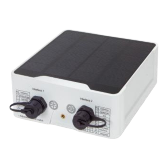
Refer to the illustration and follow the simple steps below to quickly install your LoRa Node. 3.1.1 Remove cover for setting analog input or power output When changing the analog input or power output of LN501 via DIP switch, follow the steps below: Step 1: Remove the screw caps and take off the bottom cover. - Page 6 Step 2: Choose or change an analog input and power output via DIP switch. LoRa Antenna Type-C USB Power Button LED Indicator Analog Input Power Output RS485 DIP Switch: Interface DIP Switch 12V (default) Power Output Disable 4-20mA ADC Analog Input (default) 0-10V ADC...
- Page 7 Disable Add 120 Ω resistor between A and B RS485 Add 1k Ω pull-up resistor on A Add 1k Ω pull-down resistor on B Please turn off the device before changing an analog input or power output via DIP switch. Note Power Button: Function Action LED Indication Press and hold the button for more Turn On Off On than 3s. Press and hold the button for more Turn Off On Off...
-
Page 8: Data Interface
Step 3: Put back the bottom cover and tighten the screws. 1. Analog input is set to 4-20mA by default; power output is set to 12V by default. 2. Power output on interface 1 is used for powering serial port Note devices and power output on interface 2 is used for powering analog devices and SDI-12 devices. -
Page 9: Wall Mounting
Data Interface 2 Description 5V/9V/12V OUT (Switchable) (default) Max.100mA 3.3V OUT, max. 100mA GPIO1 GPIO2 RS232(Tx)/RS485(A) RS232(Rx)/RS485(B) SDI-12 3.1.3 Wall Mounting Make sure you have a wall mounting bracket, bracket mounting screws, wall plugs, wall mounting screws and other required tools. Step 1: Mark the four holes on the wall you prefer to place the device and drill the marked four holes for the wall plugs (anchors). -
Page 10: Pole Mounting
Step 2: Place the device on the mounting bracket and put the small screw into the hole found on the bottom of the device and then tighten the screw to finish the job. 3.1.4 Pole Mounting Step 1: Straighten out the clamp and slide it through the rectangular rings in the mounting bracket, and wrap the clamp around the pole. -
Page 11: Customer Support
4. Customer Support You can browse our online FAQ resource and User’s Manual on PLANET Web site first to check if it could solve your issue. If you need more support information, please contact PLANET support team. PLANET online FAQs: https://www.planet.com.tw/en/support/faq.php?method=keyword&keyword=LN...
Need help?
Do you have a question about the LN501 and is the answer not in the manual?
Questions and answers