Planet LN501 User Manual
Lora node controller
Hide thumbs
Also See for LN501:
- User manual ,
- Quick installation manual (11 pages) ,
- Quick installation manual (9 pages)
Table of Contents
Advertisement
Quick Links
Advertisement
Table of Contents

Related Manuals for Planet LN501


Summary of Contents for Planet LN501
- Page 1 LoRa Node Controller LN501 LoRa Node Controller LN501 - 1 -...
- Page 2 Information in this User’s Manual is subject to change without notice and does not represent a commitment on the part of PLANET. PLANET assumes no responsibility for any inaccuracies that may be contained in this User’s Manual.
- Page 3 WEEE separately. Trademarks The PLANET logo is a trademark of PLANET Technology. This documentation may refer to numerous hardware and software products by their trade names. In most, if not all cases, these designations are claimed as trademarks or registered trademarks by their respective companies.
-
Page 4: Table Of Contents
LoRa Node Controller LN501 Table of Contents Chapter 1. Product Introduction ..................... 5 Package Contents ...................... 6 Overview ........................7 Features ........................8 Product Specifications ....................9 Chapter 2. Hardware Introduction ..................11 Physical Descriptions ....................11 Hardware Installation ....................14 Chapter 3. -
Page 5: Chapter 1. Product Introduction
LoRa Node Controller LN501 Chapter 1. Product Introduction Thank you for purchasing PLANET LoRa Node Controller, LN501. The descriptions of these models are as follows: LN501 Outdoor IP67 LoRa Node Controller with Solar Panel “LN501” mentioned in the manual refers to the above models. -
Page 6: Package Contents
LoRa Node Controller LN501 1.1 Package Contents The package should contain the following: LN501 LoRa Node Controller x 1 Quick Installation Guide x 1 Data Cables x 2 Mounting Bracket x 1 Wall Mounting Kits x 1 ... -
Page 7: Overview
It also bridges Modbus data between serial and Ethernet network via LoRaWAN. The LN501 supports LoRaWAN class A and C protocol to be in full compatibility with standard LoRaWAN gateways including PLANET LCG-300 series. -
Page 8: Features
LoRa Node Controller LN501 1.3 Features Key Features LN501 Easy to connect with multiple wired sensors through GPIO/AI/RS232/RS485/SDI-12 interfaces Long transmission distance up to 11km with line of sight Waterproof design including IP67 case and M12 connectors ... -
Page 9: Product Specifications
1.4 Product Specifications Product LN501 Wireless Transmission Technology LoRaWAN Antenna Internal Antenna LN501-868M: IN865, EU868, RU864 Frequency LN501-915M: US915, AU915, KR920, AS923 Tx Power 16dBm(868)/20dBm(915) Sensitivity -137dBm @300bps Work Mode OTAA/ABP Class A, Class C Data Interfaces Interface Type M12 A-Coded Male Ports 2 ×... - Page 10 LoRa Node Controller LN501 Power Connector 1 × M12 A-coded Male Interface Power Supply Solar powered + 2 x 2550mAh battery backup + 5-24 VDC Installation Desktop or wall mounting Standards Conformance Regulatory CE, FCC Compliance - 10 -...
-
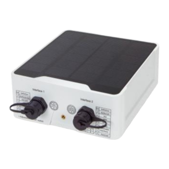
Page 11: Chapter 2. Hardware Introduction
LoRa Node Controller LN501 Chapter 2. Hardware Introduction 2.1 Physical Descriptions LN501 Analog Input Power Output - 11 -... - Page 12 LoRa Node Controller LN501 DIP Switch: Interface DIP Switch (default) Power Output Disable 4-20mA ADC Analog Input (default) 0-10V ADC Disable Add 120 Ω resistor between A and B RS485 Add 1k Ω pull-up resistor on A Add 1k Ω pull-down resistor on B 1.
- Page 13 LoRa Node Controller LN501 Data Interface: Data Interface 1 Description 5V/9V/12V OUT (Switchable) (default) 3.3V OUT, max. 100mA Analog Input 1 Analog Input 2 5-24V DC IN *When both DC external power and batteries are connected, external power will be the preferred power supply option.
-
Page 14: Hardware Installation
LoRa Node Controller LN501 2.2 Hardware Installation Refer to the illustration and follow the simple steps below to quickly install your LoRa Node. 2.2.1 Wall Mounting Make sure you have a wall mounting bracket, bracket mounting screws, wall plugs, wall mounting screws and other required tools. -
Page 15: Chapter 3. Preparation
3.1 Requirements Workstations running Windows 10/11 Type C USB cable for LN501 3.2 Managing LoRa Node Download ToolBox software from Planet web site. https://www.planet.com.tw/en/support/downloads?&method=keyword&keyword=LN501&view=6#list Power on the LoRa Node device and then connect it to computer via micro USB port. -
Page 16: Chapter 4. Operations Management
Operations Management This chapter provides operations details of the LoRa node controller. 4.1 Managing LoRa Node Download ToolBox software from Planet web site. https://www.planet.com.tw/en/support/downloads?&method=keyword&keyword=LN501&view=6#list Power on the LoRa Node device and then connect it to computer via micro USB port. - Page 17 LoRa Node Controller LN501 After logging in the ToolBox, you can click “Power On” or “Power Off” to turn on/off device and change other settings. - 17 -...
-
Page 18: Lorawan Setting
LoRa Node Controller LN501 4.2 LoRaWAN setting LoRaWAN setting is used for configuring the transmission parameters in LoRaWAN ® network. Basic LoRaWAN Settings: Go to “LoRaWAN -> Basic” of ToolBox software to configure join type, App EUI, App Key and other information. - Page 19 LoRa Node Controller LN501 Join Type OTAA and ABP mode are available Application Key Appkey for OTAA mode; default is 5572404C696E6B4C6F52613230313823. DevAddr for ABP mode, default is the 5th to 12th digits of SN. Device Address Network Session Nwkskey for ABP mode, default is 5572404C696E6B4C6F52613230313823.
- Page 20 LoRa Node Controller LN501 If frequency is one of AU915/US915, you can enter the index of the channel that you want to enable in the input box, making them separate by commas. Examples: 1, 40: Enabling Channel 1 and Channel 40...
-
Page 21: Interface Setting
LoRa Node Controller LN501 4.3 Interface setting LN501 supports data collection by multiple interfaces including GPIOs, analog inputs and serial ports. Besides, they can also power the terminal devices by power output interfaces. Basic settings are as follows: Go to “General -> Basic” of ToolBox software to change the reporting interval. -
Page 22: Rs485 Settings
LN501 4.3.1 RS485 Settings 1. Connect RS485 device to RS485 port on interface 2. If you need LN501 to power the RS485 device, please connect the power cable of RS485 device to 5V/9V/12V power output on interface 2. 2. Go to “General -> Serial” of ToolBox software to enable RS485 and configure serial port settings. - Page 23 Range: 0-600s. Power Supply Current: supply current as sensor required. Range: 0-60mA LN501 will power the RS485 terminal devices for a period of Power Output Time Before Collect time before collecting data for terminal device initialization.
- Page 24 01 03 00 00 00 01 84 0A 4. For ToolBox software, click “Fetch” to check if LN501 can read correct data from terminal devices. You can also click “Fetch” on the top of list to fetch all channel data.
-
Page 25: Rs232 Settings
LN501 4.3.2 RS232 Settings 1. Connect RS232 device to RS232 port on interface 2. If you need LN501 to power the RS232 device, connect the power cable of RS232 device to 5V/9V/12V power output on interface 1. 2. Go to “General -> Serial” of ToolBox software to enable RS232 and configure serial port settings. -
Page 26: Gpio Settings
LoRa Node Controller LN501 4.3.3 GPIO Settings 1. Connect devices to GPIO ports on interface 2. 2. Go to “General -> GPIO” of ToolBox software to enable GPIO port. 3. Select GPIO type according to your requirements. Digital Input: detect high or low status of devices ... - Page 27 After selection, click “Fetch” to check current status of digital input. Digital Output: Click “Switch” to check if LN501 can trigger devices by digital output or click “Fetch” to check the current status of digital output. - 27 -...
- Page 28 Keep Last Value When Power Keep the counted values when the device powers off. Start/Stop Make the device start/stop counting. Note: LN501 will send non-changeable counting values if you do not click“Start”. Refresh Refresh to get latest counter values. Clear Count the value from 0.
-
Page 29: Ai Settings
LN501 4.3.4 AI Settings 1. Connect analog device to analog input ports on interface 1. If you need LN501 to power the analog device, connect the power cable of analog device to 5V/9V/12V power output on interface 1. 2. Go to “General -> AI” of ToolBox software to enable analog input. - Page 30 LoRa Node Controller LN501 4. Enable “Interface 1 (Pin 1) 5V/9V/12V” and configure “Power Output Time Before Collect”, LN501 will power the analog devices for a period of time before collecting data. When you use power output to power analog devices, it only supplies power when reporting interval is coming.
-
Page 31: Sdi-12 Settings
1. Connect SDI-12 sensor to SDI-12 port on interface 2. If the SDI-12 device requires power from the LN501, connect the power cable of SDI-12 device to power output on interface 2. 2. For ToolBox software, enable SDI-12 interface and configure interface settings to be the same as those of the SDI-12 sensors. - Page 32 LoRa Node Controller LN501 When you use power output to power SDI-12 sensors, it only supplies power when reporting interval is coming. It’s suggested to power sensors with external power during the PoC test. 3. Click to add channels, click Read to get the address of this sensor.
-
Page 33: Alarm Settings
LoRa Node Controller LN501 4.4 Alarm Settings LN501 supports configuring commands to send alarm packets to network server. Each device can be added 16 threshold alarm commands at most. 1. For ToolBox software, go to Command page, click Edit to add commands. -
Page 34: Data Storage
LN501 4.5 Data Storage LN501 supports storing 600 data records locally and exports data via ToolBox software. The device will record the data according to the reporting interval even if it is not connected to a network. 1. Go to Status of ToolBox software to sync the device time;... -
Page 35: Data Retransmission
LoRa Node Controller LN501 4.6 Data Retransmission LN501 supports data retransmission to ensure the network server can get all data even if the network is down for some times. There are two ways to get the lost data: Network server sends downlink commands to enquire the historical data for specified time range, see LN501 Communication Protocol;... - Page 36 2) If the network is disconnected again during data retransmission, it will only send the latest disconnection data. 3) The retransmission data format is started with “20”, please refer to LN501 Communication Protocol. 4) Data retransmission will increase the uplinks and shorten the battery life.
-
Page 37: Maintenance
You can also click “Up to Date” to search for the latest firmware of the device and upgrade. 4.7.2 Backup LN501 devices support configuration backup for easy and quick device configuration in bulk. Backup is allowed only for devices with the same model and LoRa frequency band. Please select one of following methods to back up device: 1. -
Page 38: Reset To Factory Default
4.7.3 Reset to Factory Default Please select one of following methods to reset device: Hardware: Open the case of LN501 and hold on power button for more than 10s. ToolBox Software: Go to “Maintenance -> Backup and Reset” to click “Reset”.
Need help?
Do you have a question about the LN501 and is the answer not in the manual?
Questions and answers