Planet LN501, LN1152 - LoRa Node Controller Manual
- User manual (38 pages) ,
- Quick installation manual (11 pages) ,
- Quick installation manual (9 pages)
Advertisement
Package Contents
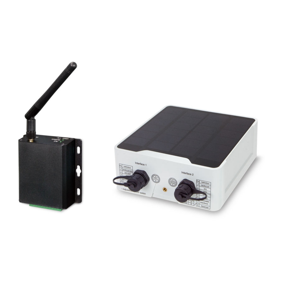
Thank you for purchasing PLANET Industrial LoRa Node Controller, LN series. The descriptions of these models are as follows:
| LN501 | Outdoor IP67 LoRa Node Controller with Solar Panel |
| LN1152 | Indoor IP30 LoRa Node Controller |
"LoRa Node" is used as an alternative name in this Quick Installation Guide.
Open the box of the LoRa Node and carefully unpack it. The box should contain the following items:
| LN501 | LN1152 |
|
|
If any item is found missing or damaged, please contact your local reseller for replacement.
 |
|
Requirements
- Workstations running Windows 10/XP/2003/Vista/7/8/2008.
- Type C USB cable for LN501.
- Micro USB cable for LN1152.
Hardware Installation
Refer to the illustration and follow the simple steps below to quickly install your LoRa Node.
LN501
Remove cover for setting analog input or power output
When changing the analog input or power output of LN501 via DIP switch, follow the steps below:
Step 1: Remove the screw caps and take off the roof cover.

Step 2: Choose or change an analog input and power output via DIP switch.

DIP Switch
| Interface | DIP Switch |
| Power Output | 12V: 1 on 2 off 3 off (default) 9V: 1 off 2 on 3 off 5V: 1 off 2 off 3 on |
| Analog Input | Disable: 1 off 2 off 3 off 4-20mA ADC: 1 off 2 on 3 on (default) 0-10V ADC: 1 on 2 off 3 off |
| RS485 | Disable: 1 off 2 off 3 off (default) Add 120 Ω resistor between A and B: 1 on 2 off 3 off Add 1k Ω pull-up resistor on A: 1 off 2 on 3 off Add 1k Ω pull-down resistor on B: 1 off 2 off 3 on |
Power Button
| Function | Action | LED Indication | |
| Turn On | Press and hold the button for more than 3s. | Off ž On On | |
| Turn Off | Press and hold the button for more than 3s. | On Off | |
| Reset | Press and hold the button for more than 10s. | Blinks. | |
| Check On/Off Status | Quickly press the power button. | Light On: Device is on. Light Off: Device is off. | |
 Note: Please turn off the device before changing DIP switches.
Step 3: Put back the roof cover and screw the screws.
Note:
- Analog input is set to 4-20mA by default; power output is set to 12V by default.
- .Power output on interface 1 is used for powering serial port devices and power output on interface 2 is used for powering analog devices.
Data Interface
Data Interface 1

| Pin | Description |
| 1 | 5V/9V/12V OUT (Switchable) |
| 2 | 3.3V OUT |
| 3 | GND |
| 4 | Analog Input 1 |
| 5 | Analog Input 2 |
| 6 | 5-24V DC IN |
Data Interface 2

| Pin | Description | |
| 1 | 5V/9V/12V OUT (Switchable) | |
| 2 | 3.3V OUT | |
| 3 | GND | |
| 4 | GPIO1 | |
| 5 | GPIO2 | |
| 6 | RS232/RS485 (Switchable) | |
| 7 | ||
| 8 | Reserved | |
| PIN | RS232 | RS485 |
| 6 | Tx | A |
| 7 | Rx | B |
Wall Mounting
Make sure you have a wall mounting bracket, bracket mounting screws, wall plugs, wall mounting screws and other required tools.
Step 1: Mark the four holes on the wall you prefer to place the device and drill the marked four holes for the wall plugs (anchors). Then place the mounting bracket over the holes with the wall plugs inside, and tighten it with the screws.
Step 2: Place the device on the mounting bracket and put the small screw into the hole found on the bottom of the device and then tighten the screw to finish the job.

Pole Mounting
Step 1: Straighten out the clamp and slide it through the rectangular rings in the mounting bracket, and wrap the clamp around the pole. Then use a screwdriver to tighten the clamp by turning it clockwise.
Step 2: Place the device on the mounting bracket and put the small screw into the hole found on the bottom of the device and then tighten the screw to finish the job.

Note: Please make sure the screws are tightly fixed.
LN1152
Antenna Installation
Step 1: Rotate the antenna into the antenna connector accordingly.
Step 2: The external LoRa antenna should be installed vertically for a good signal.

Data Interface and Power Interface

| PIN | Definition | Description | |
| 1 | GND | Ground | |
| 2 | VIN | 5-24V DC | |
| 3 | RXD | RS232 | |
| 4 | TXD | ||
| 5 | GND | ||
| 6 | A | RS485 | |
| 7 | B | ||
| 8 | IN | DI | |
| 9 | IN_COM | ||
| 10 | OUT_COM | DO | |
| 11 | OUT_NC | ||
| 12 | OUT_NO | ||
Note: OUT_NC = Normally Closed, OUT_No = Normally Open
LED Indicators
| LED | Indication | Status | Description |
| System | System Status | Static | System Start-up |
| On for 500 ms, off for 500 ms | The system is running properly. | ||
| On for 200 ms, off for 200 ms | The system is not connected to server. | ||
| ACT | Network Status | Off | Failed to access the network |
| On for 500 ms, off for 500 ms | Accessed the network successfully |
Wall Mounting
Step 1: Align the LN1152 device horizontally to the desired position on the wall and use a marker pen to mark two mounting holes on the wall.
Step 2: Drill the two holes marked previously on the wall by using your drill with a 6 mm drill bit.
Step 3: Mount the device to the wall by tightly screwing the wall mounting screws (M3 * 20) into the device mounting holes.

Wiring Power Input
LN1152 series supports 5-24V DC power supply. You can use other supplies or power adapter to power on the device.

Note: For industrial applications, it's suggested not to release the metal case and use an independent power supply.
Managing LoRa Node
- Download ToolBox software from Planet web site.
https://www.planet.com.tw/en/support/downloads?&method=keyword&keyword=LN501&view=6#list - Power on the LoRa Node device and then connect it to computer via micro USB port.

- Open the ToolBox and select "Type" and then "General", and then click password to log in ToolBox. (Default password: 123456)

- After logging in the ToolBox, you can click "Power On" or "Power Off" to turn on/off device and change other settings.


Customer Support
You can browse our online FAQ resource and User's Manual on PLANET Web site first to check if it could solve your issue. If you need more support information, please contact PLANET support team.
PLANET online FAQs:
https://www.planet.com.tw/en/support/faq.php?method=keyword&keyword=LN
Support team mail address:
support@planet.com.tw
Copyright © PLANET Technology Corp. 2022.
Contents are subject to revision without prior notice.
PLANET is a registered trademark of PLANET Technology Corp.
All other trademarks belong to their respective owners.
https://www.planet.com.tw/

Documents / Resources
References
Download manual
Here you can download full pdf version of manual, it may contain additional safety instructions, warranty information, FCC rules, etc.
Advertisement


Need help?
Do you have a question about the LN501 and is the answer not in the manual?
Questions and answers