Table of Contents
Advertisement
Quick Links
Advertisement
Table of Contents

Subscribe to Our Youtube Channel
Related Manuals for Sentera Controls TCMF8-WF Series


Summary of Contents for Sentera Controls TCMF8-WF Series
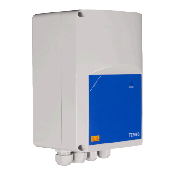
- Page 1 TCMF8-WF/EW UNIVERSAL FAN SPEED CONTROLLER Mounting and operating instructions...
-
Page 2: Table Of Contents
TCMF8-WF/EW UNIVERSAL FAN SPEED CONTROLLER Table of contents SAFETY AND PRECAUTIONS PRODUCT DESCRIPTION ARTICLE CODES INTENDED AREA OF USE TECHNICAL DATA STANDARDS WIRING AND CONNECTIONS LED INDICATIONS MOUNTING INSTRUCTIONS IN STEPS VERIFICATION OF INSTALLATION TRANSPORT AND STORAGE WARRANTY AND RESTRICTIONS MAINTENANCE MIW-TCMF8-WF-EW-EN-000 - 06 / 06 / 2023 2 - 10... -
Page 3: Safety And Precautions
TCMF8-WF/EW UNIVERSAL FAN SPEED CONTROLLER SAFETY AND PRECAUTIONS Read all the information, the datasheet, Modbus map, mounting and operating instructions and study the wiring and connection diagram before working with the product. For personal and equipment safety, and for optimum product performance, make sure you entirely understand the contents before installing, using, or maintaining this product. -
Page 4: Product Description
TCMF8-WF/EW UNIVERSAL FAN SPEED CONTROLLER PRODUCT DESCRIPTION The TCMF8-WF/EW are universal fan speed controllers with Modbus RTU communication and an integrated internet gateway. Multiple AC fans can be regulated via the two TRIAC outputs (phase angel control). Via Modbus RTU communication one or more HVAC sensors or potentiometers can be connected to this controller. -
Page 5: Standards
TCMF8-WF/EW UNIVERSAL FAN SPEED CONTROLLER STANDARDS ■ Low Voltage Directive 2014/35/EC EN 60529:1991 Degrees of protection provided by enclosures (IP Code) ► Amendment AC:1993 to EN 60529 ► EN 60730-1:2011 Automatic electrical controls for household and similar use - Part 1: General requirements EN 62311:2008 Assessment of electronic and electrical equipment related to ►... -
Page 6: Wiring And Connections
TCMF8-WF/EW UNIVERSAL FAN SPEED CONTROLLER WIRING AND CONNECTIONS Legend TCMF8-WF TCMF8-EW 10 9 Terminal block Connect the supply voltage to the input (L, N, PE). Connect the AC fans to power supply and the outputs taking into account the maximum current. regulated outputs Terminal block If applicable, analogue input signals and motor TK contacts (thermal... -
Page 7: Led Indications
TCMF8-WF/EW UNIVERSAL FAN SPEED CONTROLLER Wiring and connections Supply voltage, Line Supply voltage, Neutral Protective Earth Regulated motor output 1 Regulated motor output 2 TK1, TK2 Thermal contact inputs Modbus RTU (RS485) signal A Modbus RTU (RS485) signal /B Ai1, Ai2 Analogue input 0—10 VDC / 0—20 mA / PWM Ground Cable cross section... - Page 8 TCMF8-WF/EW UNIVERSAL FAN SPEED CONTROLLER Insert the cables through the cable glands and do the wiring according to the wiring diagram (see “Wiring and connections“ ) while adhering to the information from section “Wiring and connections”. ► Connect the AC fans (terminals U2, U1 and PE); Connect the supply voltage (terminals L, N and PE);...
- Page 9 TCMF8-WF/EW UNIVERSAL FAN SPEED CONTROLLER Download and Install Sentera Solution Firmware The TCMF8 controller requires application dedicated firmware, which can be downloaded from the Sentera website: Select your application via www.sentera. eu/en/solutions. First, connect all required products including the Sentera internet gateway. Then connect your installation to www.senteraweb.eu.
-
Page 10: Verification Of Installation
TCMF8-WF/EW UNIVERSAL FAN SPEED CONTROLLER VERIFICATION OF INSTALLATION After connecting the unit to the main supply, the green LED on its cover should light up to indicate that the controller is supplied. Safe operation depends on proper installation. Before start up, ensure the following: ■...
Need help?
Do you have a question about the TCMF8-WF Series and is the answer not in the manual?
Questions and answers