Advertisement
Quick Links
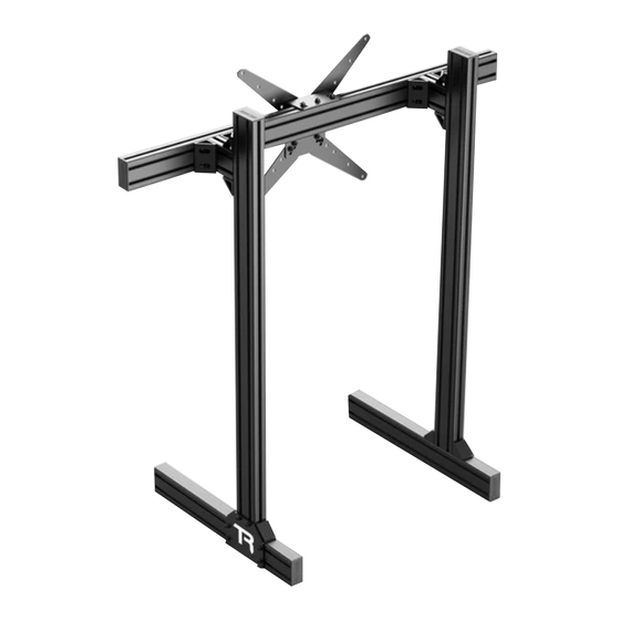
Floor Single Monitor
Stand with VESA Mount
(800mm Crossbar)
Assembly Guide
IMPORTANT: As there are different versions of each rig depending on your
region, please ensure that you are using the correct instruction set. The
part number below should match the part number labeled on your box
MS-SML-FM
Published 2023‑09‑06
1
Advertisement

Subscribe to Our Youtube Channel
Related Manuals for TRAK RACER MS-SML-FM


Summary of Contents for TRAK RACER MS-SML-FM
- Page 1 Assembly Guide IMPORTANT: As there are different versions of each rig depending on your region, please ensure that you are using the correct instruction set. The part number below should match the part number labeled on your box MS-SML-FM Published 2023‑09‑06...
- Page 2 TABLE OF CONTENTS Symbol Legend Part list Assembly Notes MS-SML-FM Assembly Instructions...
- Page 3 IMPORTANT: As there are different versions of each rig depending on your region, please ensure that you are using the correct instruction set. The part number below should match the part number labeled on your box IMPORTANT: Due to the nature of cut aluminium profile, some metal shavings may still be present after our extensive QA cleaning process.
- Page 4 IMPORTANT: As there are different versions of each rig depending on your region, please ensure that you are using the correct instruction set. The part number below should match the part number labeled on your box MS-SML-FM PARTS LIST Description Part #...
-
Page 5: Back Side
NOTE BACK SIDE FRONTSIDE INSIDE TOP SIDE OUTSIDE INSTALLATAION ORDER FOR SCREWS & WASHERS HOW TO MEASURE SCREWS ① SCREW ② LOCK WASHER ③ WASHER (IF APPLICABLE) FLAT SCREW HEX SCREW BUTTON SCREW... - Page 6 The handle screws (SL-M8-20 & SL-M8-25) are NOTE ratcheted to allow for tightening and loosening when space for rotation is limited. Simply pull the handle out and turn handle into position and push handle back in to engage thread.
- Page 7 NOTE tooltip NS-M8 & NS-M6 tooltip It is strongly advised that spring T-Nuts are inserted by sliding from the ends of profiles. Please take careful note of each step of all T-nuts as some are to be installed in anticipation of future steps. tooltip tooltip If T-Nuts are skipped, and...
- Page 8 NOTE BC-40...
- Page 9 M6x16mm AL-80-600 NS-M8 NS-M6 SH-M6-16 FR-01 tooltip tooltip NOTE: Rubber feet and hardware are optional. tooltip tooltip Insert 4pcs of NS-M8 into OUTSIDE of each of AL-80-600 (for STEP 2b) M8x20mm AL-80-1200 NS-M8 SH-M8-20 WL-M8 WF-M8 BP-80-V Insert 1pcs of NS-M8 into FRONT &...
- Page 10 M8x20mm BC-40 NS-M8 SH-M8-20 WL-M8 WF-M8 tooltip tooltip M8x16mm tooltip AL-80-105 NS-M8 SH-M8-16 BA-40-BLK...
- Page 11 tooltip M8x16mm NS-M8 SH-M8-16 BA-80-BLK Ensure corner brackets are facing inward M8x16mm AL-80-800 NS-M8 SH-M8-16 tooltip 60mm 600mm 60mm...
- Page 12 M8x20mm VM-02 NS-M8 SH-M8-20 WL-M8 WF-M8 M8x16mm tooltip VM-02-A VM-02-B SF-M8-16 NF-M8 NOTE: Optional for larger monitors. If monitor mounting points are 150mm or 200mm apart, add VESA extensions (VM-02-E)
- Page 13 tooltip NOTE: If installing Arms for triple monitors, skip this step until assembly of all other components is complete. EC-80 BC-40 NOTE: Tape measure and scissors not supplied tooltip PS-600-R PS-1200-R...
- Page 14 tooltip IMPORTANT: If your monitor screws are under 8mm (M8), you will need to use washers (not supplied)
- Page 15 FINISHED Share your build online and tag us to be featured! @trakracer @trakracer @trak_racer...
Need help?
Do you have a question about the MS-SML-FM and is the answer not in the manual?
Questions and answers