
Related Manuals for Pickering 40-855A


Summary of Contents for Pickering 40-855A
- Page 1 40/42-855A User Manual PXI/PXIe MEMS Fiber Optic Switch Module pickeringtest.com Issue 1.3 November 2022...
- Page 2 © COPYRIGHT (2022) PICKERING INTERFACES. ALL RIGHTS RESERVED. No part of this publication may be reproduced, transmitted, transcribed, translated or stored in any form, or by any means without the written permission of Pickering Interfaces. Technical details contained within this publication are subject to change without notice.
- Page 3 Pickering Interfaces strives to fulfil all relevant environmental laws and regulations and reduce wastes and releases to the environment. Pickering Interfaces aims to design and operate products in a way that protects the environment and the health and safety of its employees, customers and the public. Pickering Interfaces endeavours to develop and manufacture products that can be produced, distributed, used and recycled, or disposed of, in a safe and environmentally friendly manner.
-
Page 4: Product Safety
PRODUCT SAFETY SAFETY SYMBOLS The following safety symbols may be used on the product and throughout the product documentation. MEANING / DESCRIPTION SYMBOL PROTECTIVE EARTH (GROUND) To identify any terminal which is intended for connection to an external conductor for protection against electric shock in case of a fault, or the terminal of a protective earth (ground) electrode. -
Page 5: Table Of Contents
Pre Operation Checks ............3.1 Hardware Installation ............3.2 Software Installation .............3.2 Testing Operation ..............3.3 Section 4 Programming Guide ..............4.1 Programming Options For Pickering PXI/PXIe Modules ...4.1 Module Architecture ..............4.2 Programming The Module ............4.3 Section 5 Connector Information ..............5.1 Section 6 Trouble Shooting .................6.1 Section 7 Maintenance Information ............7.1... - Page 6 THIS PAGE INTENTIONALLY BLANK MEMS FIBER OPTIC SWITCH MODULE 40/42-855A Page (VI)
-
Page 7: Warnings And Cautions
Unused slots in the PXI/LXI chassis are populated with blanking plates to prevent access to user I/O signals that may be present. Blanking panels are available to order from Pickering in a variety of slot widths. If the product is not used in this manner for example by using an extender card then additional care must be taken to avoid contact with exposed signals. - Page 8 SAFETY INSTRUCTIONS SAFETY INSTRUCTIONS All cleaning and servicing requires the equipment to be isolated and disconnected from the power source and user I/O signals (refer to the Maintenance Section). • Appropriate manual handling procedures should be followed as dictated by the weight of the individual module or the combined weight of the modules &...
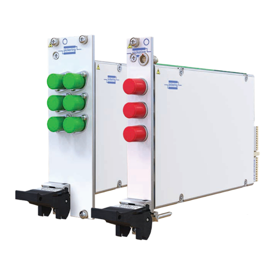
- Page 9 Hardware Interlock Option y 3 Year Warranty The 40-855A (PXI) and 42-855A (PXIe) are 2-channel MEMS Pickering can construct custom optical systems to fiber optic multiplexers available in single, dual, triple or customers precise requirements. We have a large range...
- Page 10 Mechanical Characteristics Polarization dependent loss (PDL): 0.05 dB Max 40-855A - 3 U PXI (CompactPCI card). Single or dual slot as indicated in Product Order Codes. Power Requirements - 40-855A 42-855A - 3 U PXIe, compatible with PXIe hybrid slot. Single +3.3 V...
- Page 11 SECTION 1 - TECHNICAL SPECIFICATION pickering Specifications & Ordering Information MEMS Fiber Optic Switch, 40/42-855A PXI & CompactPCI Compliance - 40-855A Operating/Storage Conditions The module is compliant with the PXI Specification 2.2. Operating Conditions Local Bus, Trigger Bus & Star Trigger are not implemented.
- Page 12 PXIe MU (mini SC) Product Customization Support Products Interlock Connectors Pickering modules are designed and manufactured on our own flexible manufacturing lines, giving complete product For modules with the hardware interlock option control and enabling simple customization to meet very (40/42-855A-xx2-HI) spare/replacement connectors can specific requirements.
- Page 13 We provide a full range of supporting cable and connector solutions for all our switching products—20 connector families with 1200+ products. We offer everything from simple mating connectors to complex cables assemblies and terminal blocks. All assemblies are manufactured by Pickering and are guaranteed to mechanically and electrically mate to our modules. Connectors & Backshells...
- Page 14 MEMS Fiber Optic Switch, 40/42-855A Programming Pickering provide kernel, IVI and VISA (NI & Keysight) drivers which are compatible with all Microsoft supported versions of Windows and popular older versions. For a list of all supporting operating systems, please see: pickeringtest.com/os...
-
Page 15: Technical Description
SECTION 2 - TECHNICAL DESCRIPTION pickering SECTION 2 - TECHNICAL DESCRIPTION FUNCTIONAL DESCRIPTION A functional block diagram is provided in Figure 2.1. The module is powered by +5V (PXI), +3.3V and +12V supplies via PCI Bus or PXIe Bus connectors mounted on a mother board. The interface to the user test equipment is via fiber connectors mounted on the front panel. -
Page 16: Hardware Interlock
SECTION 2 - TECHNICAL DESCRIPTION pickering HARDWARE INTERLOCK The 40/42-855A-xxx-HI modules have an interlock feature that can be used to return the optical switches (assuming they are fully functional) to their default unpowered state if the interlock connector is not in place or if the connection between the two interlock pins is open-circuit. - Page 17 SECTION 2 - TECHNICAL DESCRIPTION pickering +3.3V +3.3V +3.3V 40/42-855A-xxx-HI 40/42-855A-xxx-HI 40/42-855A-xxx-HI Optical Optical Optical Enable Enable Enable Switch Switch Switch Module Module Module Status Status Status PXI Gnd PXI Gnd PXI Gnd To Other Modules With Hardware Interlock All Modules Enabled by a Common Signal MASTER +3.3V...
- Page 18 SECTION 2 - TECHNICAL DESCRIPTION pickering THIS PAGE INTENTIONALLY BLANK MEMS FIBER OPTIC SWITCH MODULE 40/42-855A Page 2.4...
-
Page 19: Installation
Modular products require installation in a suitable PXI/PXIe/LXI chassis. The module is for indoor use only. PREOPERATION CHECKS (UNPACKING) 1. Check the module for transport damage and report any damage immediately to Pickering Interfaces. Do not attempt to install the product if any damage is evident. -
Page 20: Hardware Installation
For a system comprising more than one chassis, turn ON the last chassis in the system followed by the penultimate, etc, and finally turn ON the external controller or chassis containing the system controller. 9. For Pickering Interfaces modular LXI installation there is no requirement to use any particular power up sequence. -
Page 21: Testing Operation
Figure 3.2 - General Soft Front Panel Icon A selector panel will appear, listing all installed Pickering PCI, PXI or LXI switch cards and resistor cards. Click on the card you wish to control, and a graphical control panel is presented allowing operation of the card. - Page 22 SECTION 3 - INSTALLATION pickering THIS PAGE INTENTIONALLY BLANK MEMS FIBER OPTIC SWITCH MODULE 40/42-855A Page 3.4...
-
Page 23: Programming Guide
SECTION 4 - PROGRAMMING GUIDE PROGRAMMING OPTIONS FOR PICKERING INTERFACES PXI/PXIe MODULES For information on the installation and use of drivers and the programming of Pickering’s products in various software environments, please refer to the Software User Manual. This is available as a download from: https://www.pickeringtest.com/support/software-drivers-and-downloads... -
Page 24: Module Architecture
SECTION 4 - PROGRAMMING GUIDE pickering MODULE ARCHITECTURE The 40/42-855A is a 2 channel optical switch module with one, two, three or four separate banks using MEMS switches. In the default unpowered state, the Common to Channel 1 path is selected. Energising a particular MEMS switch breaks the signal path between Common and Channel 1 and creates a signal path between Common and Channel 2. -
Page 25: Programming The Module
SECTION 4 - PROGRAMMING GUIDE pickering PROGRAMMING THE MODULE Here are examples of using the drivers with the 40/42-855A-x22 (dual 2-channel switch) module. The single, triple and quad versions operates in a similar way but has a different number of bits in the sub-unit. - Page 26 SECTION 4 - PROGRAMMING GUIDE pickering THIS PAGE INTENTIONALLY BLANK MEMS FIBER OPTIC SWITCH MODULE 40/42-855A Page 4.4...
- Page 27 SECTION 5 - CONNECTOR INFORMATION pickering SECTION 5 - CONNECTOR INFORMATION Single 2-Channel Fiber Optic Switch pickering pickering pickering pickering pickering 40/42-855A-012 40/42-855A-312 40/42-855A-412 40/42-855A-512-M 40/42-855A-212 (FC/APC) (MU) (LC) (ST) (SC/PC) 40/42-855A-112 40/42-855A-212-M (FC/PC) (SC) Figure 5.1 - Single 2-Channel Fiber Optic Switch Module 40/42-855A: Connector Positions MEMS FIBER OPTIC SWITCH MODULE 40/42-855A Page 5.1...
- Page 28 SECTION 5 - CONNECTOR INFORMATION pickering Dual 2-Channel Fiber Optic Switch pickering pickering pickering pickering pickering C1 C2 40/42-855A-022 40/42-855A-222 40/42-855A-322 40/42-855A-422 40/42-855A-522-M (FC/APC) (SC/PC) (MU) (LC) (ST) 40/42-855A-122 40/42-855A-222-M (FC/PC) (SC) Figure 5.2 - Dual 2-Channel Fiber Optic Switch Module 40/42-855A: Connector Positions MEMS FIBER OPTIC SWITCH MODULE 40/42-855A Page 5.2...
- Page 29 SECTION 5 - CONNECTOR INFORMATION pickering +3.3V (link to pin 2 Ground to allow operation) Status (daisy-chain Enable (link to pin 1 connection to to allow operation) subsequent modules) Figure 5.3 - Pinout: Hardware Interlock Connector Applicable to 40/42-855A-xxx-HI Modules With Hardware Interlock Option (4-pin 00 Series Female Connector Viewed From Front of Module) Note: the maximum conductor size for the interlock connector is 30AWG.
- Page 30 SECTION 5 - CONNECTOR INFORMATION pickering THIS PAGE INTENTIONALLY BLANK MEMS FIBER OPTIC SWITCH MODULE 40/42-855A Page 5.4...
-
Page 31: Trouble Shooting
PCI configuration, highlighting any potential configuration problems. Specific details of all installed Pickering switch cards are included. All the installed Pickering switch cards should be listed in the “Pilpxi information” section - if one or more cards is missing it may be possible to determine the reason by referring to the PCI configuration dump contained in the report, but interpretation of this information is far from straightforward, and the best course is to contact Pickering support: support@pickeringtest.com, if possible... - Page 32 SECTION 6 - TROUBLE SHOOTING pickering THIS PAGE INTENTIONALLY BLANK MEMS FIBER OPTIC SWITCH MODULE 40/42-855A Page 6.2...
-
Page 33: Maintenance Information
For PXI modules which are supported in one of Pickering Interfaces’ Modular LXI Chassis (such as the 60-102B and 60-103B) no module software update is required. If the module was introduced after the LXI chassis was manufactured the module may not be recognized, in this case the chassis firmware may need upgrading. - Page 34 SECTION 7 - MAINTENANCE INFORMATION pickering Table 7.1 - Fiber Optic Switch Module 40/42-855A: Switch Numbering Switch No. Switch No. Switch No. Signal Path 40/42-855A-x12 40/42-855A-022/122 40/42-855A-222 Com1 to Channel 1 (default) Com1 to Channel 2 Com2 to Channel 1 (default) —...
Need help?
Do you have a question about the 40-855A and is the answer not in the manual?
Questions and answers