Table of Contents
Advertisement
Quick Links
www.ti.com
EVM User's Guide: DS320PR410-RSC-EVM
DS320PR410-RSC-EVM Evaluation Module
Description
The DS320PR410-RSC-EVM evaluation module
provides a complete high-bandwidth platform for
evaluating the signal conditioning features of
the Texas Instruments DS320PR410 Four-Channel
PCI-Express 5.0 Linear Redriver. This evaluation
board can be used for standard compliance
testing, performance evaluation, and initial system
prototyping.
Get Started
1. Order the DS320PR410-RSC-EVM on
2. Read through the instructions provided in this
User's Guide to understand the jumper options
provided on the DS320PR410-RSC-EVM and for
instructions to configure the EVM.
3. For EEPROM or SMBus / I
the TI
SigCon Architect
the Texas Instruments SigCon Architect GUI. To
download the DS320PR410 SigCon Architect GUI
profile, please contact your TI representative or
create a request using
SNLU334 – DECEMBER 2023
Submit Document Feedback
ti.com
2
C programming, visit
download page to install
TI
E2E.
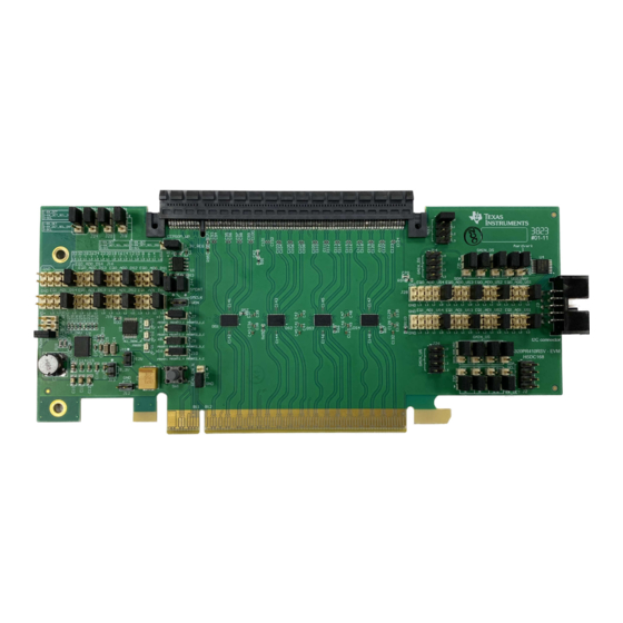
DS320PR410-RSC-EVM – Top Side View
Copyright © 2023 Texas Instruments Incorporated
Features
•
PCIe x16 Riser Card option with eight 4-channel
unidirectional linear redrivers operating at rates up
to 32Gbps
•
Linear equalization for seamless support of link
training and PCIe channel extension
•
CTLE boosts up to 22 dB at 16 GHz
•
Programmable device configuration through
2
EEPROM, GPIO, I
C, or SMBus
•
Onboard 12-V to 3.3-V, 2-A step-down DC/DC
converter
•
Industrial temperature range: –40°C to 85°C
•
Flow-through layout in 4 mm × 6 mm, 40-pin, lead-
less WQFN 0.4-mm pitch package
Applications
•
PCI Express Gen-1, 2, 3, 4, and 5
•
High-speed interfaces up to 32Gbps
•
Enterprise server motherboard, workstation
•
Enterprise storage
•
Enterprise add-in card, end-point
DS320PR410-RSC-EVM Evaluation Module
Description
1
Advertisement
Table of Contents

Related Manuals for Texas Instruments DS320PR410-RSC-EVM


Summary of Contents for Texas Instruments DS320PR410-RSC-EVM
-
Page 1: Description
2. Read through the instructions provided in this less WQFN 0.4-mm pitch package User's Guide to understand the jumper options Applications provided on the DS320PR410-RSC-EVM and for instructions to configure the EVM. • PCI Express Gen-1, 2, 3, 4, and 5 3. -
Page 2: Table Of Contents
4.3 Bill of Materials.................................23 5 Additional Information................................27 6 References.................................... List of Figures Figure 1-1. DS320PR410-RSC-EVM Example Application Diagram..................Figure 2-1. SigCon Architect DS320PR410 High-Level Page....................Figure 3-1. Example Test Setup..............................Figure 3-2. Example Test Results..............................14 Figure 4-1. Control and Status Schematic Page........................ -
Page 3: Evaluation Module Overview
1.3 Specification The DS320PR410-RSC-EVM is targeted for applications where PCI-Express riser card slots (up to x16) are available for test. Figure 1-1 shows the DS320PR410-RSC-EVM used with a system motherboard with a PCI-Express Gen5.0 capable CPU and an Add-In Card Endpoint. -
Page 4: Hardware
Hardware www.ti.com 2 Hardware The Hardware section details DS320PR410-RSC-EVM hardware control features, the SMBus / I C control interface, and quick-start guidelines. 2.1 DS320PR410 5-Level I/O Control Inputs Each DS320PR410 features 5-level input pins (MODE, GAIN, RX_DET, EQ0 / ADDR0, and EQ1 / ADDR1) that are used to control the configuration of the device. -
Page 5: Ds320Pr410 Smbus Or I
ADDR0 Pin Level [HEX] 0x18 0x1A 0x1C 0x1E Reserved 0x20 0x22 0x24 0x26 Reserved 0x28 0x2A 0x2C 0x2E Reserved 0x30 0x32 0x34 0x36 Reserved SNLU334 – DECEMBER 2023 DS320PR410-RSC-EVM Evaluation Module Submit Document Feedback Copyright © 2023 Texas Instruments Incorporated... -
Page 6: Ds320Pr410 Equalization Control
The equalization gain of each channel of each device can also be set by writing to SMBus / I C registers in I Mode. Refer to the DS320PR410 Programming Guide for details. DS320PR410-RSC-EVM Evaluation Module SNLU334 – DECEMBER 2023 Submit Document Feedback Copyright © 2023 Texas Instruments Incorporated... -
Page 7: Ds320Pr410 Rx Detect State Machine
The DC gain of each channel of each device can also be set by writing to SMBus / I C registers in Secondary or Primary Modes. Refer to the DS320PR410 Programming Guide for details. SNLU334 – DECEMBER 2023 DS320PR410-RSC-EVM Evaluation Module Submit Document Feedback Copyright © 2023 Texas Instruments Incorporated... -
Page 8: Ds320Pr410 Evm Global Controls
Hardware www.ti.com 2.7 DS320PR410 EVM Global Controls Table 2-7 shows DS320PR410-RSC-EVM global controls that affect all devices on the board. Table 2-7. EVM Global Controls COMPONENT NAME FUNCTION / DESCRIPTION MODE control tied to MODE pins of all eight DS320PR410 devices on the EVM... -
Page 9: Ds320Pr410-Rsc-Evm Downstream Devices Control
Hardware 2.8 DS320PR410-RSC-EVM Downstream Devices Control Table 2-8 shows the DS320PR410-RSC-EVM downstream device controls that affect DS1, DS2, DS3, and DS4 devices on the board. Table 2-8. EVM Downstream Devices Controls COMPONENT NAME FUNCTION / DESCRIPTION Gain Controls tied to GAIN pins of all downstream device banks (GAIN_DS) L0: –6 dB Gain Setting... -
Page 10: Ds320Pr410-Rsc-Evm Upstream Devices Control
Install shunt across pins 2-3 for operation in SMBus, I C Modes 2.9 DS320PR410-RSC-EVM Upstream Devices Control Table 2-9 shows DS320PR410-RSC-EVM upstream devices controls that affect US1, US2, US3, and US4 devices on the board. Table 2-9. EVM Upstream Devices Controls COMPONENT... -
Page 11: Quick-Start Guide (Pin Mode)
EVM or configured for hot-plug operation. 10. Install a compatible PCIe endpoint card into the straddle connector of the EVM. 11. Power-up the motherboard. SNLU334 – DECEMBER 2023 DS320PR410-RSC-EVM Evaluation Module Submit Document Feedback Copyright © 2023 Texas Instruments Incorporated... -
Page 12: Quick-Start Guide
BER, etc.), the PCIe link must be re-trained by toggling PERST# or by performing a warm reset (without removing power to the DS320PR410). DS320PR410-RSC-EVM Evaluation Module SNLU334 – DECEMBER 2023 Submit Document Feedback Copyright © 2023 Texas Instruments Incorporated... -
Page 13: Figure 2-1. Sigcon Architect Ds320Pr410 High-Level Page
Hardware Figure 2-1. SigCon Architect DS320PR410 High-Level Page SNLU334 – DECEMBER 2023 DS320PR410-RSC-EVM Evaluation Module Submit Document Feedback Copyright © 2023 Texas Instruments Incorporated... -
Page 14: Test Setup And Results
Figure 3-1. As the result indicates, the end point (Nvidia / Mellanox NIC) with the DS320PR410-RSC-EVM placed in the data path achieves a stable Gen5, x16 PCIe link. Figure 3-2. Example Test Results DS320PR410-RSC-EVM Evaluation Module SNLU334 –... -
Page 15: Hardware Design Files
PERST_INV 2-3 = Aardvark 1.0k 10.0k 10.0k 10.0k 3_3V_REG 1.0k SEL1 C Connector SEL2 SEL3 5103311-1 TMUX1133PWR Figure 4-1. Control and Status Schematic Page SNLU334 – DECEMBER 2023 DS320PR410-RSC-EVM Evaluation Module Submit Document Feedback Copyright © 2023 Texas Instruments Incorporated... -
Page 16: Figure 4-2. Voltage Regulator Schematic Page
VSEL ILIM 165k 37.4k 42.2k RESV_TRK PGND PGND PGND PGND 2.05k PGND PGND PGND DRGND PGND AGND TPS548B22RVFR Figure 4-2. Voltage Regulator Schematic Page DS320PR410-RSC-EVM Evaluation Module SNLU334 – DECEMBER 2023 Submit Document Feedback Copyright © 2023 Texas Instruments Incorporated... -
Page 17: Figure 4-3. Gold Finger Connector Schematic Page
Oh m should be 50 Ohms (up to the PRSNT2_4 RSVD3 PRSNT2_1 43 Oh m resis tor) RSVD4 RSVD1 Figure 4-3. Gold Finger Connector Schematic Page SNLU334 – DECEMBER 2023 DS320PR410-RSC-EVM Evaluation Module Submit Document Feedback Copyright © 2023 Texas Instruments Incorporated... -
Page 18: Figure 4-4. Downstream Devices Schematic Page
MODE R108 75.0k RX_DET RX_DET C139 C140 PWDN TSW-117-08-L-D 0.1uF 0.1uF 0.1uF 0.1uF PWDN READ_EN_N READ_EN_N DONE_N_DS DONE_N_DS Figure 4-4. Downstream Devices Schematic Page DS320PR410-RSC-EVM Evaluation Module SNLU334 – DECEMBER 2023 Submit Document Feedback Copyright © 2023 Texas Instruments Incorporated... -
Page 19: Figure 4-5. Upstream Devices Schematic Page
C128 C129 C130 C131 C132 C147 C148 0.1uF 0.1uF PWDN TSW-117-08-L-D 0.1uF 0.1uF PWDN DONE_N_DS DONE_N_DS DONE_N DONE_N Figure 4-5. Upstream Devices Schematic Page SNLU334 – DECEMBER 2023 DS320PR410-RSC-EVM Evaluation Module Submit Document Feedback Copyright © 2023 Texas Instruments Incorporated... -
Page 20: Figure 4-6. Straddle Connector Schematic Page
C104 C124 PER5_P PER15_P PER5_N PER15_N PRSNT2_4_C PET6C_P PET6_C_P RSVD 0.22uF C105 10163106-A41410HLF 10163106-A41410HLF 10163106- A41410HLF 10163106- A41410HLF Figure 4-6. Straddle Connector Schematic Page DS320PR410-RSC-EVM Evaluation Module SNLU334 – DECEMBER 2023 Submit Document Feedback Copyright © 2023 Texas Instruments Incorporated... -
Page 21: Figure 4-7. Hardware Page
These assemblies must be clean and free from flux and all contaminants. Use of no clean flux is not acceptable. Assembly Note These assemblies must comply with workmanship standards IPC-A-610 Class 2, unless otherwise specified. Figure 4-7. Hardware Page SNLU334 – DECEMBER 2023 DS320PR410-RSC-EVM Evaluation Module Submit Document Feedback Copyright © 2023 Texas Instruments Incorporated... -
Page 22: Board Layout
Hardware Design Files www.ti.com 4.2 Board Layout Figure 4-8 Figure 4-9 illustrate the EVM board layouts. Figure 4-8. Top Layer Figure 4-9. Bottom Layer DS320PR410-RSC-EVM Evaluation Module SNLU334 – DECEMBER 2023 Submit Document Feedback Copyright © 2023 Texas Instruments Incorporated... -
Page 23: Bill Of Materials
C126, C127, C132 C38, C39, C43, C44, C48, C49, 0.1uF CAP, CERM, 0.1 uF, 6.3 V, +/- 10%, X5R, 0402S C1005X5R0J104K050BA C130, C131 0402 SNLU334 – DECEMBER 2023 DS320PR410-RSC-EVM Evaluation Module Submit Document Feedback Copyright © 2023 Texas Instruments Incorporated... - Page 24 THT-14-423-10 Brady 0.200" H - 10,000 per roll R3, R4 2.2k RES, 2.2 k, 5%, 0.063 W, AEC-Q200 Grade 0402 CRCW04022K20JNED Vishay-Dale 0, 0402 DS320PR410-RSC-EVM Evaluation Module SNLU334 – DECEMBER 2023 Submit Document Feedback Copyright © 2023 Texas Instruments Incorporated...
- Page 25 RES, 4.70 k, 1%, 0.063 W, 0402 0402 CRG0402F4K7 TE Connectivity R67, R110 R62, R70 6.19k RES, 6.19 k, 1%, 0.063 W, AEC-Q200 Grade 0402 CRCW04026K19FKED Vishay-Dale 0, 0402 SNLU334 – DECEMBER 2023 DS320PR410-RSC-EVM Evaluation Module Submit Document Feedback Copyright © 2023 Texas Instruments Incorporated...
- Page 26 3 Circuit IC Switch 2:1 4Ohm 16-TSSOP PW0016A-MFG TMUX1133PWR Texas Instruments FID1, FID2, FID3 Fiducial mark. There is nothing to buy or Fiducial10-20 mount. DS320PR410-RSC-EVM Evaluation Module SNLU334 – DECEMBER 2023 Submit Document Feedback Copyright © 2023 Texas Instruments Incorporated...
-
Page 27: Additional Information
Additional Information 5 Additional Information Trademarks All trademarks are the property of their respective owners. SNLU334 – DECEMBER 2023 DS320PR410-RSC-EVM Evaluation Module Submit Document Feedback Copyright © 2023 Texas Instruments Incorporated... -
Page 28: References
For references, see the following: 1. Texas Instruments, DS320PR410 Four-Channel Linear Redriver for PCI-Express 5.0, CXL 2.0 data sheet. 2. Texas Instruments, DS320PR410 Programming Guide DS320PR410-RSC-EVM Evaluation Module SNLU334 – DECEMBER 2023 Submit Document Feedback Copyright © 2023 Texas Instruments Incorporated... - Page 29 STANDARD TERMS FOR EVALUATION MODULES Delivery: TI delivers TI evaluation boards, kits, or modules, including any accompanying demonstration software, components, and/or documentation which may be provided together or separately (collectively, an “EVM” or “EVMs”) to the User (“User”) in accordance with the terms set forth herein.
- Page 30 www.ti.com Regulatory Notices: 3.1 United States 3.1.1 Notice applicable to EVMs not FCC-Approved: FCC NOTICE: This kit is designed to allow product developers to evaluate electronic components, circuitry, or software associated with the kit to determine whether to incorporate such items in a finished product and software developers to write software applications for use with the end product.
- Page 31 www.ti.com Concernant les EVMs avec antennes détachables Conformément à la réglementation d'Industrie Canada, le présent émetteur radio peut fonctionner avec une antenne d'un type et d'un gain maximal (ou inférieur) approuvé pour l'émetteur par Industrie Canada. Dans le but de réduire les risques de brouillage radioélectrique à...
- Page 32 www.ti.com EVM Use Restrictions and Warnings: 4.1 EVMS ARE NOT FOR USE IN FUNCTIONAL SAFETY AND/OR SAFETY CRITICAL EVALUATIONS, INCLUDING BUT NOT LIMITED TO EVALUATIONS OF LIFE SUPPORT APPLICATIONS. 4.2 User must read and apply the user guide and other available documentation provided by TI regarding the EVM prior to handling or using the EVM, including without limitation any warning or restriction notices.
- Page 33 Notwithstanding the foregoing, any judgment may be enforced in any United States or foreign court, and TI may seek injunctive relief in any United States or foreign court. Mailing Address: Texas Instruments, Post Office Box 655303, Dallas, Texas 75265 Copyright © 2023, Texas Instruments Incorporated...
- Page 34 TI products. TI’s provision of these resources does not expand or otherwise alter TI’s applicable warranties or warranty disclaimers for TI products. TI objects to and rejects any additional or different terms you may have proposed. IMPORTANT NOTICE Mailing Address: Texas Instruments, Post Office Box 655303, Dallas, Texas 75265 Copyright © 2023, Texas Instruments Incorporated...
Need help?
Do you have a question about the DS320PR410-RSC-EVM and is the answer not in the manual?
Questions and answers