Table of Contents
Advertisement
Quick Links
www.ti.com
User's Guide
DS320PR412-421EVM User's Guide
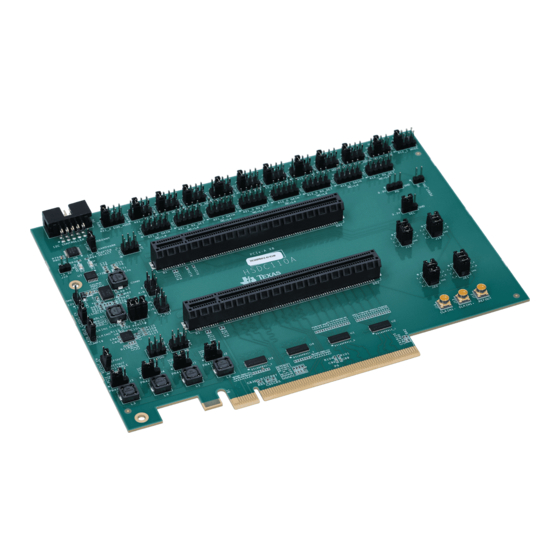
The DS320PR412-421EVM evaluation module provides a complete high-bandwidth platform for evaluating the
signal conditioning features of the DS320PR412, DS320PR421, SN75LVPE5412 and SN75LVPE5421 Quad-
Channel PCI Express 5.0 Linear Redrivers with integrated Mux/Demux. This evaluation board can be used for
standard compliance testing, performance evaluation, and initial system prototyping.
Note: In this document, all instances of DS320PR412 can be interchangeable with SN75LVPE5412 and all
instances of DS320PR421 are interchangeable with SN75LVPE5421.
1
Introduction.............................................................................................................................................................................3
1.1 Features.............................................................................................................................................................................
1.2
Applications........................................................................................................................................................................3
2 Description..............................................................................................................................................................................
2.2 Redriver-Mux Modes of Operation.....................................................................................................................................
2.3 Redriver-Mux SMBus or I2C Register Control Interface....................................................................................................
2.4 Redriver-Mux Equalization Control....................................................................................................................................
2.5 Redriver-Mux RX Detect State Machine............................................................................................................................
2.6 Redriver-Mux DC Gain Control..........................................................................................................................................
2.7 DS320PR412-421EVM Global Controls............................................................................................................................
2.9 DS320PR412-421EVM Upstream Devices Control...........................................................................................................
2.10 Quick-Start Guide (Pin Mode)........................................................................................................................................
SNLU301 - NOVEMBER 2021
Submit Document Feedback
ABSTRACT
Figure 1-1. DS320PR412-421EVM
Table of Contents
Inputs............................................................................................................................4
Control.......................................................................................................8
Copyright © 2021 Texas Instruments Incorporated
Table of Contents
DS320PR412-421EVM User's Guide
3
4
4
4
5
5
6
7
9
10
1
Advertisement
Table of Contents

Subscribe to Our Youtube Channel
Related Manuals for Texas Instruments DS320PR412-421EVM


Summary of Contents for Texas Instruments DS320PR412-421EVM
-
Page 1: Table Of Contents
DS320PR412-421EVM User's Guide ABSTRACT The DS320PR412-421EVM evaluation module provides a complete high-bandwidth platform for evaluating the signal conditioning features of the DS320PR412, DS320PR421, SN75LVPE5412 and SN75LVPE5421 Quad- Channel PCI Express 5.0 Linear Redrivers with integrated Mux/Demux. This evaluation board can be used for standard compliance testing, performance evaluation, and initial system prototyping. - Page 2 Table 2-10. Pin Mode Shunt Configuration..........................Table 2-11. SMBus/I2C Mode Shunt Configuration........................11 Table 5-1. DS320PR412-421 Bill of Materials........................... Trademarks All trademarks are the property of their respective owners. DS320PR412-421EVM User's Guide SNLU301 – NOVEMBER 2021 Submit Document Feedback Copyright © 2021 Texas Instruments Incorporated...
-
Page 3: Introduction
Introduction 1 Introduction The DS320PR412-421EVM features two DS320PR412 and two DS320PR421 linear redrivers that can extend the transmission distance of a PCIe Gen-5 x8 bus. The EVM can be directly plugged into a PCIe slot on a server or PC motherboard using the PCIe Edge connector on the board and paired with a PCIe add-in card using one of the two PCIe connectors on the EVM. -
Page 4: Description
EQ0/ADDR Pin Level 7-Bit Address [HEX] 7-Bit Address [HEX] 0x18 0x19 0x1A 0x1B 0x1C 0x1D 0x1E 0x1F 0x20 0x21 0x22 0x23 0x24 0x25 0x26 0x27 DS320PR412-421EVM User's Guide SNLU301 – NOVEMBER 2021 Submit Document Feedback Copyright © 2021 Texas Instruments Incorporated... -
Page 5: Redriver-Mux Equalization Control
The RX_DET/SCL pin of DS320PR412, DS320PR421, SN75LVPE5412 and SN75LVPE5421 provides additional flexibility to system designers to appropriately set the device in their desired mode, according Table 2-5. SNLU301 – NOVEMBER 2021 DS320PR412-421EVM User's Guide Submit Document Feedback Copyright © 2021 Texas Instruments Incorporated... -
Page 6: Redriver-Mux Dc Gain Control
The DC gain of each channel of each device can also be set by writing to SMBus / I2C registers in Slave or Master Modes. DS320PR412-421EVM User's Guide SNLU301 – NOVEMBER 2021 Submit Document Feedback Copyright © 2021 Texas Instruments Incorporated... -
Page 7: Ds320Pr412-421Evm Global Controls
1-2 : Disabled 2-3: Enabled JMP19 CLK Buffer Input Sel 1-2 : CLKIN1 2-3: CLKIN0 JMP20 CLK Buffer Ref. Out 1-2 : Enabled 2-3: Disabled SNLU301 – NOVEMBER 2021 DS320PR412-421EVM User's Guide Submit Document Feedback Copyright © 2021 Texas Instruments Incorporated... -
Page 8: Ds320Pr412-421Evm Downstream Devices Control
Description www.ti.com 2.8 DS320PR412-421EVM Downstream Devices Control Table 2-8 shows DS320PR412-421EVM downstream devices controls that affect DS1 and DS2 devices on the board. Table 2-8. EVM Downstream Devices Controls COMPONENT NAME FUNCTION OR DESCRIPTION 1-2: L0 3-4: L1 DS320PR412_0 JMP1... -
Page 9: Ds320Pr412-421Evm Upstream Devices Control
Description 2.9 DS320PR412-421EVM Upstream Devices Control Table 2-9 shows DS320PR412-421EVM upstream devices controls that affect US1-US2 devices on the board. Table 2-9. EVM Upstream Devices Controls COMPONENT NAME FUNCTION OR DESCRIPTION JMP9 DS320PR421_0 1-2: L0 3-4: L1 5-6: L27-8: L3 N/C: L4... -
Page 10: Quick-Start Guide (Pin Mode)
8. Install a compatible PCIe endpoint card into one of the PCIe connectors on the EVM based on configuration of the SEL pin. Note: PCIe-A requires enabling bifurcation on the motherboard. 9. Power-up the motherboard. DS320PR412-421EVM User's Guide SNLU301 – NOVEMBER 2021 Submit Document Feedback Copyright © 2021 Texas Instruments Incorporated... -
Page 11: Quick-Start Guide (Smbus Slave Mode)
1. Connect USB2ANY or Aardvark Adapter to P4 (Note that the Adapter is not supplied with the DS320PR412-421EVM). Install shunt on JMP17 across pins 1-2 for USB2ANY, 3-4 for Aardvark. 2. Install SigCon Architect Version 3.0.0.16 application and the DS320PR412-421 profile. -
Page 12: Figure 2-1. Sigcon Architect Ds320Pr412-421 High Level Page
10. Select the devices to which you want to apply the selected settings and click the Apply to All Channels button. Figure 2-1. SigCon Architect DS320PR412-421 High Level Page DS320PR412-421EVM User's Guide SNLU301 – NOVEMBER 2021 Submit Document Feedback Copyright © 2021 Texas Instruments Incorporated... -
Page 13: Schematics
Schematics 3 Schematics Figure 3-1 through Figure 3-9 show the EVM schematics. Figure 3-1. DS320PR412 SNLU301 – NOVEMBER 2021 DS320PR412-421EVM User's Guide Submit Document Feedback Copyright © 2021 Texas Instruments Incorporated... -
Page 14: Figure 3-2. Ds320Pr421
Schematics www.ti.com Figure 3-2. DS320PR421 DS320PR412-421EVM User's Guide SNLU301 – NOVEMBER 2021 Submit Document Feedback Copyright © 2021 Texas Instruments Incorporated... -
Page 15: Figure 3-3. Configuration Headers
Schematics Figure 3-3. Configuration Headers Figure 3-4. I2C Adapter Selection SNLU301 – NOVEMBER 2021 DS320PR412-421EVM User's Guide Submit Document Feedback Copyright © 2021 Texas Instruments Incorporated... -
Page 16: Figure 3-5. Power
Schematics www.ti.com Figure 3-5. Power DS320PR412-421EVM User's Guide SNLU301 – NOVEMBER 2021 Submit Document Feedback Copyright © 2021 Texas Instruments Incorporated... -
Page 17: Figure 3-6. Edge Finger
Schematics Figure 3-6. EDGE Finger SNLU301 – NOVEMBER 2021 DS320PR412-421EVM User's Guide Submit Document Feedback Copyright © 2021 Texas Instruments Incorporated... -
Page 18: Figure 3-7. Pcie Clock
Schematics www.ti.com Figure 3-7. PCIe Clock Figure 3-8. PCIe x8 Connector A DS320PR412-421EVM User's Guide SNLU301 – NOVEMBER 2021 Submit Document Feedback Copyright © 2021 Texas Instruments Incorporated... -
Page 19: Figure 3-9. Pcie X16 Connector B
Schematics Figure 3-9. PCIe x16 Connector B SNLU301 – NOVEMBER 2021 DS320PR412-421EVM User's Guide Submit Document Feedback Copyright © 2021 Texas Instruments Incorporated... -
Page 20: Pcb Layouts
PCB Layouts www.ti.com 4 PCB Layouts Figure 4-1 through Figure 4-6 illustrate the EVM PCB layout images. Figure 4-1. Top Layer Figure 4-2. Layer 2 DS320PR412-421EVM User's Guide SNLU301 – NOVEMBER 2021 Submit Document Feedback Copyright © 2021 Texas Instruments Incorporated... -
Page 21: Figure 4-3. Layer 3
PCB Layouts Figure 4-3. Layer 3 Figure 4-4. Layer 4 SNLU301 – NOVEMBER 2021 DS320PR412-421EVM User's Guide Submit Document Feedback Copyright © 2021 Texas Instruments Incorporated... -
Page 22: Figure 4-5. Layer 5
PCB Layouts www.ti.com Figure 4-5. Layer 5 Figure 4-6. Bottom Layer DS320PR412-421EVM User's Guide SNLU301 – NOVEMBER 2021 Submit Document Feedback Copyright © 2021 Texas Instruments Incorporated... -
Page 23: Bill Of Materials
6.8uH Eaton Header 5x2 0.1" Shroud RA thru-hole R1,R5,R9,R13,R17,R21,R25,R29,R3 Panasonic Electronic ERJ-2GEJ102X 1,R32,R33,R34,R35,R36,R37,R38,R Components 41,R45,R49,R53,R65,R69,R73,R77, R78,R120,R133,R137,R141,R145,R R2,R6,R10,R14,R18,R22,R26,R30,R 8.25K Panasonic Electronic ERJ-2RKF8251X 42,R46,R50,R62,R66,R70,R74,R134 Components ,R138,R142,R146,R150 SNLU301 – NOVEMBER 2021 DS320PR412-421EVM User's Guide Submit Document Feedback Copyright © 2021 Texas Instruments Incorporated... - Page 24 Panasonic Electronic ERA-2AED101X Components R121,R122,R123,R124,R125,R126, Yageo RC0402FR-071RL R127,R128,R129,R130 SHNT1,SHNT2,SHNT3,SHNT4,SHN QPC02SXGN-RC Sullins Connector T5,SHNT6,SHNT7,SHNT8,SHNT9,S Solutions HNT10,SHNT11,SHNT12,SHNT13,S HNT14,SHNT15,SHNT16,SHNT17,S HNT18,SHNT19,SHNT20,SHNT21,S HNT22,SHNT23,SHNT24,SHNT25,S HNT26 U1,U2 DS320PR412 or Texas Instruments SN75LVPE5412 DS320PR412-421EVM User's Guide SNLU301 – NOVEMBER 2021 Submit Document Feedback Copyright © 2021 Texas Instruments Incorporated...
- Page 25 Part Manufacturer Part Number U3,U4 DS320PR421 or Texas Instruments SN75LVPE5421 TMUX1133PWR Texas Instruments TPS548B22RVFT Texas Instruments TPS548B22RVFT SN74LVC125A_PW_1 Texas Instruments SN74LVC125AQPWRQ1 LMK00334RTVR Texas Instruments SNLU301 – NOVEMBER 2021 DS320PR412-421EVM User's Guide Submit Document Feedback Copyright © 2021 Texas Instruments Incorporated...
- Page 26 STANDARD TERMS FOR EVALUATION MODULES Delivery: TI delivers TI evaluation boards, kits, or modules, including any accompanying demonstration software, components, and/or documentation which may be provided together or separately (collectively, an “EVM” or “EVMs”) to the User (“User”) in accordance with the terms set forth herein.
- Page 27 www.ti.com Regulatory Notices: 3.1 United States 3.1.1 Notice applicable to EVMs not FCC-Approved: FCC NOTICE: This kit is designed to allow product developers to evaluate electronic components, circuitry, or software associated with the kit to determine whether to incorporate such items in a finished product and software developers to write software applications for use with the end product.
- Page 28 www.ti.com Concernant les EVMs avec antennes détachables Conformément à la réglementation d'Industrie Canada, le présent émetteur radio peut fonctionner avec une antenne d'un type et d'un gain maximal (ou inférieur) approuvé pour l'émetteur par Industrie Canada. Dans le but de réduire les risques de brouillage radioélectrique à...
- Page 29 www.ti.com EVM Use Restrictions and Warnings: 4.1 EVMS ARE NOT FOR USE IN FUNCTIONAL SAFETY AND/OR SAFETY CRITICAL EVALUATIONS, INCLUDING BUT NOT LIMITED TO EVALUATIONS OF LIFE SUPPORT APPLICATIONS. 4.2 User must read and apply the user guide and other available documentation provided by TI regarding the EVM prior to handling or using the EVM, including without limitation any warning or restriction notices.
- Page 30 Notwithstanding the foregoing, any judgment may be enforced in any United States or foreign court, and TI may seek injunctive relief in any United States or foreign court. Mailing Address: Texas Instruments, Post Office Box 655303, Dallas, Texas 75265 Copyright © 2019, Texas Instruments Incorporated...
- Page 31 TI products. TI’s provision of these resources does not expand or otherwise alter TI’s applicable warranties or warranty disclaimers for TI products. TI objects to and rejects any additional or different terms you may have proposed. IMPORTANT NOTICE Mailing Address: Texas Instruments, Post Office Box 655303, Dallas, Texas 75265 Copyright © 2021, Texas Instruments Incorporated...
Need help?
Do you have a question about the DS320PR412-421EVM and is the answer not in the manual?
Questions and answers