
Related Manuals for Texas Instruments DS110DF111EVM


Summary of Contents for Texas Instruments DS110DF111EVM
- Page 1 DS110DF111EVM Evaluation Board User's Guide Literature Number: SNLU142A May 2014 – Revised January 2016...
-
Page 2: Table Of Contents
SMBus Slave Mode ......................EEPROM Mode ........................EVM Layout ......................... Schematic ........................Bill of Materials ......................Example Waveforms .......................... Revision History Table of Contents SNLU142A – May 2014 – Revised January 2016 Submit Documentation Feedback Copyright © 2014–2016, Texas Instruments Incorporated... - Page 3 Four-Level Logic Settings ....................DS110DF111 VOD Levels ....................DS110DF111 DEM Levels ................... DS110DF111 Loopback Control ..................SMBus Write Address Assignment SNLU142A – May 2014 – Revised January 2016 List of Figures Submit Documentation Feedback Copyright © 2014–2016, Texas Instruments Incorporated...
-
Page 4: Overview
SNLU142A – May 2014 – Revised January 2016 DS110DF111EVM Evaluation Board Overview The DS110DF111EVM – SMA evaluation kit provides a complete high band-width platform to evaluate the signal integrity and signal conditioning features of the Texas Instruments signal conditioning products – with Equalization and De-emphasis. -
Page 5: Features
Front Port Optical Interconnects • SFF-8431 • 10G/1G Ethernet • CPRI Ordering Information EVM ID DEVICE ID DEVICE PACKAGE DS110DF111EVM DS110DF111SQ 24WQFN SNLU142A – May 2014 – Revised January 2016 DS110DF111EVM Evaluation Board Submit Documentation Feedback Copyright © 2014–2016, Texas Instruments Incorporated... -
Page 6: Setup
This section describes the jumpers and connectors on the EVM, as well and how to properly connect, set up and use the DS110DF111EVM. The DS110DF111EVM – SMA evaluation kit can be used in three different modes. 1. Pin Control Mode – provides access to selected signal integrity settings. -
Page 7: Ds110Df111 Vod Levels
Setup www.ti.com 5.1.1 Pin Control Mode Configuration The DS110DF111EVM is shipped ready to use in pin control mode. The EVM will require the following power supply inputs and jumpers. 1. J17 - GND 2. J19 – V to V : 3.3 V supply operation, 2.5 V internal regulator is enabled 3. -
Page 8: Ds110Df111 Loopback Control
There are no pin control settings for the input Equalization. The DS110DF111 input equalization will automatically adapt for divide ratios 1 and 2. For divide ratios 4 and 8 a pre-set equalization level is used. 5.1.4 Loopback J6 and J61 control the DS110DF111EVM loopback function according to Table Table 4. DS110DF111 Loopback Control Loopback... -
Page 9: Smbus Slave Mode
SCL | SDA | GND DS1xxDF111EVM DPS-DONGLE-EVM Figure 3. DS1xxDF111EVM Slave Mode Full Setup Figure 4. DS1xxDF111EVM Slave Mode Close-Up SNLU142A – May 2014 – Revised January 2016 DS110DF111EVM Evaluation Board Submit Documentation Feedback Copyright © 2014–2016, Texas Instruments Incorporated... -
Page 10: Ds110Df111 High Level Page
5.2.2 Using SigCon Architect SigCon Architect can be used to program the DS110DF111EVM. In order to use SigCon Architect for SMBus Slave Mode access control, a DPS-DONGLE-EVM (see SNLU184) or USB2ANY equivalent adapter board must be used. This adapter board serves as an interface board to allow SMBus communication between the PC and the DS110DF111 retimer. -
Page 11: Ds110Df111 Low Level Page
"SigCon Architect: Installation and Starter's Guide" (SNLU178) and the "DS110DF410EVK, DS110DF410EVK, and DS125DF410EVM Evaluation Board Software Installation, Setup, and Operating Guide" (SNLU126). SNLU142A – May 2014 – Revised January 2016 DS110DF111EVM Evaluation Board Submit Documentation Feedback Copyright © 2014–2016, Texas Instruments Incorporated... -
Page 12: Eeprom Mode
"Understanding EEPROM Programming for 10G to 12.5G Retimers" (SNLA245) and the "DS110DF410EVK, DS110DF410EVK, and DS125DF410EVM Evaluation Board Software Installation, Setup, and Operating Guide" (SNLU126). DS110DF111EVM Evaluation Board SNLU142A – May 2014 – Revised January 2016 Submit Documentation Feedback Copyright © 2014–2016, Texas Instruments Incorporated... -
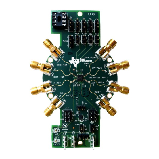
Page 13: Evm Layout
DS110DF111EVM. The EVM uses simple 100 mil headers to control the output signal integrity functions. The DS110DF111EVM is very compact and low power, the board traces have been designed for connection to standard 50 Ω test equipment and cables. -
Page 14: Schematic
25 MHz Oscillator LOCKED = ON (GREEN) J161 ADDR0 0.1u D1 SML-310PTT86 WM6502-ND LOSS of SIGNAL = ON (GREEN) D2 SML-310PTT86 DS110DF111EVM Evaluation Board SNLU142A – May 2014 – Revised January 2016 Submit Documentation Feedback Copyright © 2014–2016, Texas Instruments Incorporated... -
Page 15: Bill Of Materials
(DNP) RES 50 OHM 0402 Rohm MCR01MZPF49R9 R30, R32, R34 (DNP) RES 1K OHM 0402 Rohm MCR01MZPJ102 DS110DF111EVM, PCB, 0.062 inch Rev 1 SNLU142A – May 2014 – Revised January 2016 DS110DF111EVM Evaluation Board Submit Documentation Feedback Copyright © 2014–2016, Texas Instruments Incorporated... -
Page 16: Example Waveforms
EVM with matched SMA coaxial cables. Figure 11. 10.3125 Gbps Output Waveform DS110DF111EVM Evaluation Board SNLU142A – May 2014 – Revised January 2016 Submit Documentation Feedback Copyright © 2014–2016, Texas Instruments Incorporated... - Page 17 Example Waveforms www.ti.com Figure 12. 10.3125 Gbps RjDj Jitter Decomposition SNLU142A – May 2014 – Revised January 2016 DS110DF111EVM Evaluation Board Submit Documentation Feedback Copyright © 2014–2016, Texas Instruments Incorporated...
-
Page 18: Revision History
Changed display format of EVM layout NOTE: Page numbers for previous revisions may differ from page numbers in the current version. Revision History SNLU142A – May 2014 – Revised January 2016 Submit Documentation Feedback Copyright © 2014–2016, Texas Instruments Incorporated... - Page 19 STANDARD TERMS AND CONDITIONS FOR EVALUATION MODULES Delivery: TI delivers TI evaluation boards, kits, or modules, including any accompanying demonstration software, components, or documentation (collectively, an “EVM” or “EVMs”) to the User (“User”) in accordance with the terms and conditions set forth herein. Acceptance of the EVM is expressly subject to the following terms and conditions.
- Page 20 FCC Interference Statement for Class B EVM devices NOTE: This equipment has been tested and found to comply with the limits for a Class B digital device, pursuant to part 15 of the FCC Rules. These limits are designed to provide reasonable protection against harmful interference in a residential installation.
- Page 21 【無線電波を送信する製品の開発キットをお使いになる際の注意事項】 開発キットの中には技術基準適合証明を受けて いないものがあります。 技術適合証明を受けていないもののご使用に際しては、電波法遵守のため、以下のいずれかの 措置を取っていただく必要がありますのでご注意ください。 1. 電波法施行規則第6条第1項第1号に基づく平成18年3月28日総務省告示第173号で定められた電波暗室等の試験設備でご使用 いただく。 2. 実験局の免許を取得後ご使用いただく。 3. 技術基準適合証明を取得後ご使用いただく。 なお、本製品は、上記の「ご使用にあたっての注意」を譲渡先、移転先に通知しない限り、譲渡、移転できないものとします。 上記を遵守頂けない場合は、電波法の罰則が適用される可能性があることをご留意ください。 日本テキサス・イ ンスツルメンツ株式会社 東京都新宿区西新宿6丁目24番1号 西新宿三井ビル 3.3.3 Notice for EVMs for Power Line Communication: Please see http://www.tij.co.jp/lsds/ti_ja/general/eStore/notice_02.page 電力線搬送波通信についての開発キットをお使いになる際の注意事項については、次のところをご覧くださ い。http://www.tij.co.jp/lsds/ti_ja/general/eStore/notice_02.page SPACER EVM Use Restrictions and Warnings: 4.1 EVMS ARE NOT FOR USE IN FUNCTIONAL SAFETY AND/OR SAFETY CRITICAL EVALUATIONS, INCLUDING BUT NOT LIMITED TO EVALUATIONS OF LIFE SUPPORT APPLICATIONS.
- Page 22 Notwithstanding the foregoing, any judgment may be enforced in any United States or foreign court, and TI may seek injunctive relief in any United States or foreign court. Mailing Address: Texas Instruments, Post Office Box 655303, Dallas, Texas 75265 Copyright © 2015, Texas Instruments Incorporated...
- Page 23 IMPORTANT NOTICE Texas Instruments Incorporated and its subsidiaries (TI) reserve the right to make corrections, enhancements, improvements and other changes to its semiconductor products and services per JESD46, latest issue, and to discontinue any product or service per JESD48, latest issue.
Need help?
Do you have a question about the DS110DF111EVM and is the answer not in the manual?
Questions and answers