
Subscribe to Our Youtube Channel
Related Manuals for Texas Instruments DS80PCI810EVM


Summary of Contents for Texas Instruments DS80PCI810EVM
- Page 1 DS80PCI810EVM Evaluation Board User's Guide Literature Number: SNLU171 September 2014...
-
Page 2: Table Of Contents
........................Applications ......................Ordering Information ........................ 4-Level IO Control ................DS80PCI810EVM Configuration Overview ......................Quick Start Guide ........................Bill of Materials ......................... Schematic ........................EVM Layout Contents SNLU171 – September 2014 Submit Documentation Feedback Copyright © 2014, Texas Instruments Incorporated... - Page 3 ................. 3-4. EQA and EQB Settings Available in Pin Mode ................3-5. VOD Output Settings available in Pin Mode ......................4-1. Bill of Materials SNLU171 – September 2014 List of Figures Submit Documentation Feedback Copyright © 2014, Texas Instruments Incorporated...
-
Page 4: Overview
SNLU171 – September 2014 Overview The DS80PCI810EVM – SMA evaluation kit provides a complete high bandwidth platform to evaluate the PCIe signal conditioning features of the Texas Instruments DS80PCI810 repeater/redriver. The DS80PCI810EVM can be used for standard compliance testing, performance evaluation, and initial system prototyping. -
Page 5: Ds80Pci810Evm Front
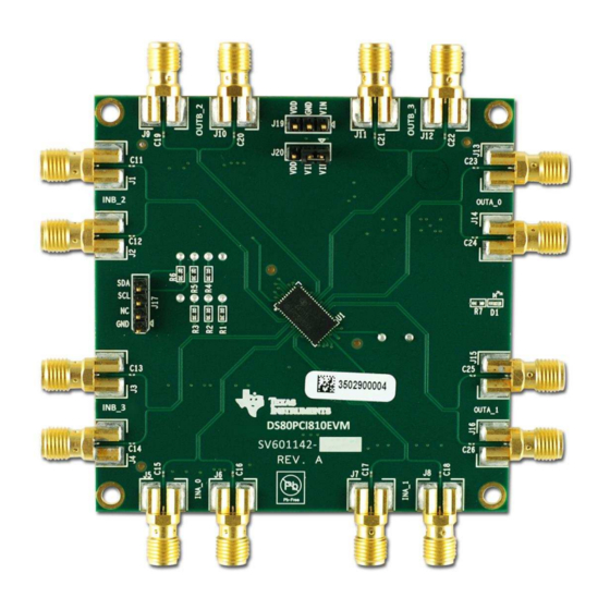
Ordering Information www.ti.com Figure 1-1. DS80PCI810EVM Front Figure 1-2. DS80PCI810EVM Back SNLU171 – September 2014 Overview Submit Documentation Feedback Copyright © 2014, Texas Instruments Incorporated... -
Page 6: 4-Level Io Control
The following switches are used to set the input condition for 4-level inputs: SW1, SW2, SW3, SW5, SW6, SW8, and SW9. The switch configurations for each of the 4-level inputs are shown in Table 2-2. Note the notation in descending order. 4-Level IO Control SNLU171 – September 2014 Submit Documentation Feedback Copyright © 2014, Texas Instruments Incorporated... -
Page 7: Switch Configuration
NOTE: Since each 4-level input setting is controlled by a set of three adjacent switches, only one of the three switches can be in the ON position at any time. SNLU171 – September 2014 4-Level IO Control Submit Documentation Feedback Copyright © 2014, Texas Instruments Incorporated... -
Page 8: Ds80Pci810Evm Configuration Overview
The following tables describe the various connectors and user-controllable settings available on the DS80PCI810EVM. Since the device can operate in one of three modes (pin mode, SMBus slave mode, and SMBus master mode), note the switch description that matches the intended mode of operation. For more information about specific EQ, VOD, and SD_TH values, see the DS80PCI810 datasheet. -
Page 9: Quick Start Guide
V (see Figure 1-1) • For 2.5 V mode: V tied to V (see Figure 1-1) 3. Set the control switches for normal operation: SNLU171 – September 2014 DS80PCI810EVM Configuration Overview Submit Documentation Feedback Copyright © 2014, Texas Instruments Incorporated... -
Page 10: Sma Channel Connections
3-switch settings for the 4-level input. • [Example] Set VODB[1:0] to Level 4: SW5 (6-5-4), (3-2-1) = (OFF-ON-OFF), (OFF-OFF-OFF) = VODB[1:0] = R, F DS80PCI810EVM Configuration Overview SNLU171 – September 2014 Submit Documentation Feedback Copyright © 2014, Texas Instruments Incorporated... -
Page 11: Vod Output Settings Available In Pin Mode
Afterwards, the DS80PCI810 releases control of the SDA/SCL line and all EQ, VOD, and VOD_DB levels become controllable via SMBus slave registers in accordance to the SMBus register map in the DS80PCI810 datasheet. SNLU171 – September 2014 DS80PCI810EVM Configuration Overview Submit Documentation Feedback Copyright © 2014, Texas Instruments Incorporated... -
Page 12: Bill Of Materials
SWITCH TAPE SEAL 2 POS SMD SW10 P12225STB-ND EVQ-21505R SWITCH LT 6MM 160GF 5MM HEIGHT DS80PCI810NJY BUFFER - REPEATER CONN JUMPER SHORTING GOLD S9001-ND SPC02SYAN FLASH Bill of Materials SNLU171 – September 2014 Submit Documentation Feedback Copyright © 2014, Texas Instruments Incorporated... -
Page 13: Schematic
Chapter 5 SNLU171 – September 2014 Schematic Figure 5-1. Schematic SNLU171 – September 2014 Schematic Submit Documentation Feedback Copyright © 2014, Texas Instruments Incorporated... -
Page 14: Evm Layout
Figure 6-2 show the DS80PCI810EVM layout. The evaluation board uses switches to control signal integrity settings. The DS80PCI810EVM allows access to the inner four buffer repeater channels while remaining both very compact and low power. The WQFN package offers an exposed thermal pad to enhance electrical and thermal performance. -
Page 15: Bottom Assembly Layer
Figure 6-2. Bottom Assembly Layer SNLU171 – September 2014 EVM Layout Submit Documentation Feedback Copyright © 2014, Texas Instruments Incorporated... - Page 16 STANDARD TERMS AND CONDITIONS FOR EVALUATION MODULES Delivery: TI delivers TI evaluation boards, kits, or modules, including any accompanying demonstration software, components, or documentation (collectively, an “EVM” or “EVMs”) to the User (“User”) in accordance with the terms and conditions set forth herein. Acceptance of the EVM is expressly subject to the following terms and conditions.
- Page 17 FCC Interference Statement for Class B EVM devices NOTE: This equipment has been tested and found to comply with the limits for a Class B digital device, pursuant to part 15 of the FCC Rules. These limits are designed to provide reasonable protection against harmful interference in a residential installation.
- Page 18 【無線電波を送信する製品の開発キットをお使いになる際の注意事項】 開発キットの中には技術基準適合証明を受けて いないものがあります。 技術適合証明を受けていないもののご使用に際しては、電波法遵守のため、以下のいずれかの 措置を取っていただく必要がありますのでご注意ください。 1. 電波法施行規則第6条第1項第1号に基づく平成18年3月28日総務省告示第173号で定められた電波暗室等の試験設備でご使用 いただく。 2. 実験局の免許を取得後ご使用いただく。 3. 技術基準適合証明を取得後ご使用いただく。 なお、本製品は、上記の「ご使用にあたっての注意」を譲渡先、移転先に通知しない限り、譲渡、移転できないものとします。 上記を遵守頂けない場合は、電波法の罰則が適用される可能性があることをご留意ください。 日本テキサス・イ ンスツルメンツ株式会社 東京都新宿区西新宿6丁目24番1号 西新宿三井ビル 3.3.3 Notice for EVMs for Power Line Communication: Please see http://www.tij.co.jp/lsds/ti_ja/general/eStore/notice_02.page 電力線搬送波通信についての開発キットをお使いになる際の注意事項については、次のところをご覧くださ い。http://www.tij.co.jp/lsds/ti_ja/general/eStore/notice_02.page SPACER EVM Use Restrictions and Warnings: 4.1 EVMS ARE NOT FOR USE IN FUNCTIONAL SAFETY AND/OR SAFETY CRITICAL EVALUATIONS, INCLUDING BUT NOT LIMITED TO EVALUATIONS OF LIFE SUPPORT APPLICATIONS.
- Page 19 Notwithstanding the foregoing, any judgment may be enforced in any United States or foreign court, and TI may seek injunctive relief in any United States or foreign court. Mailing Address: Texas Instruments, Post Office Box 655303, Dallas, Texas 75265 Copyright © 2015, Texas Instruments Incorporated...
- Page 20 IMPORTANT NOTICE Texas Instruments Incorporated and its subsidiaries (TI) reserve the right to make corrections, enhancements, improvements and other changes to its semiconductor products and services per JESD46, latest issue, and to discontinue any product or service per JESD48, latest issue.
- Page 21 Mouser Electronics Authorized Distributor Click to View Pricing, Inventory, Delivery & Lifecycle Information: Texas Instruments DS80PCI810EVM...
Need help?
Do you have a question about the DS80PCI810EVM and is the answer not in the manual?
Questions and answers