Table of Contents
Advertisement
Quick Links
www.ti.com
User's Guide
DS320PR810-RSC-EVM User's Guide
The DS320PR810-RSC-EVM evaluation modules provides a complete high-bandwidth platform for evaluating
the signal conditioning features of the Texas Instruments DS320PR810 Octal-Channel PCI-Express 5.0 Linear
Redriver. This evaluation board can be used for standard compliance testing, performance evaluation, and initial
system prototyping.
1
Introduction.............................................................................................................................................................................3
1.1 Features.............................................................................................................................................................................
1.2
Applications........................................................................................................................................................................3
2 Description..............................................................................................................................................................................
2.1 DS320PR810 5-Level I/O Control Inputs...........................................................................................................................
2.4 DS320PR810 Equalization Control....................................................................................................................................
2.9 DS320PR810EVM Upstream Devices Control................................................................................................................
2.10 Quick-Start Guide (Pin Mode)........................................................................................................................................
2.11 Quick-Start Guide (SMBus Slave Mode)........................................................................................................................
3 Test Setup and Results........................................................................................................................................................
4
Schematics............................................................................................................................................................................14
Layout.........................................................................................................................................................................22
6 Bill of Materials.....................................................................................................................................................................
7 References............................................................................................................................................................................
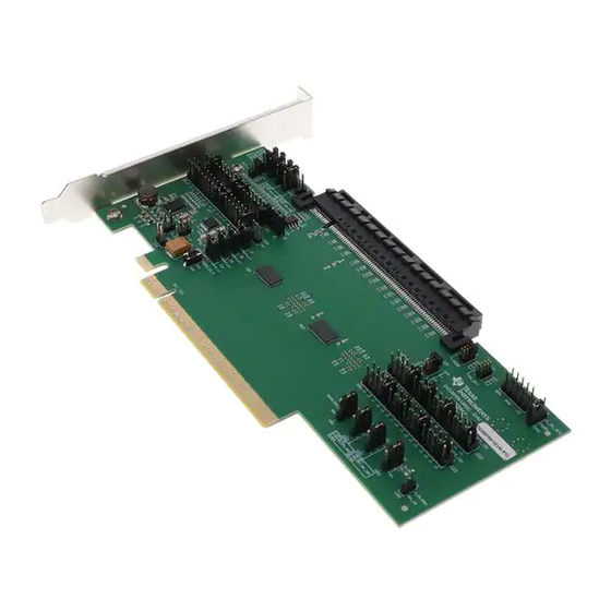
Figure 1-1. DS320PR810-RSC-EVM - Top Side View................................................................................................................
Figure 2-1. SigCon Architect DS320PR810 High-Level Page...................................................................................................
Figure 3-1. Example Test Setup................................................................................................................................................
Results..............................................................................................................................................13
Figure 4-2. Control and Status Schematic Page.......................................................................................................................
SNLU297 - MAY 2021
Submit Document Feedback
ABSTRACT
Figure 1-1. DS320PR810-RSC-EVM - Top Side View
Table of Contents
Operation.....................................................................................................................................4
Interface....................................................................................................5
Machine............................................................................................................................7
Control..........................................................................................................................................7
..................................................................................................................................8
Control..............................................................................................................9
List of Figures
Page......................................................................................................................................14
Page.........................................................................................................................16
Copyright © 2021 Texas Instruments Incorporated
Table of Contents
3
4
4
6
10
11
11
13
23
26
1
12
13
15
1
Advertisement
Table of Contents

Subscribe to Our Youtube Channel
Related Manuals for Texas Instruments DS320PR810-RSC-EVM


Summary of Contents for Texas Instruments DS320PR810-RSC-EVM
-
Page 1: Table Of Contents
ABSTRACT The DS320PR810-RSC-EVM evaluation modules provides a complete high-bandwidth platform for evaluating the signal conditioning features of the Texas Instruments DS320PR810 Octal-Channel PCI-Express 5.0 Linear Redriver. This evaluation board can be used for standard compliance testing, performance evaluation, and initial system prototyping. - Page 2 Table 2-8. EVM Downstream Devices Controls...........................9 Table 2-9. EVM Upstream Devices Controls..........................Table 6-1. Bill of Materials................................23 Trademarks All trademarks are the property of their respective owners. DS320PR810-RSC-EVM User's Guide SNLU297 – MAY 2021 Submit Document Feedback Copyright © 2021 Texas Instruments Incorporated...
-
Page 3: Introduction
Introduction 1 Introduction The DS320PR810-RSC-EVM evaluation module features four DS320PR810 linear redrivers that can extend the transmission distance of a PCIe Gen-5 x16 bus. The evaluation module can directly be plugged into a PCIe slot on a server or PC motherboard using one end of the board, and paired up with a PCIe add-in card using the straddle mount connector attached to the other end of the board. -
Page 4: Description
Table 2-2. Modes of Operation MODE PIN LEVEL MODE OF OPERATION Pin Mode SMBus Mode or I2C Master Mode SMBus Mode or I2C Slave Mode RESERVED RESERVED DS320PR810-RSC-EVM User's Guide SNLU297 – MAY 2021 Submit Document Feedback Copyright © 2021 Texas Instruments Incorporated... -
Page 5: Ds320Pr810 Smbus Or I2C Register Control Interface
0x26 0x27 Reserved Reserved 0x28 0x29 0x2A 0x2B 0x2C 0x2D 0x2E 0x2F Reserved Reserved 0x30 0x31 0x32 0x33 0x34 0x35 0x36 0x37 Reserved Reserved SNLU297 – MAY 2021 DS320PR810-RSC-EVM User's Guide Submit Document Feedback Copyright © 2021 Texas Instruments Incorporated... -
Page 6: Ds320Pr810 Equalization Control
The equalization gain of each channel of each device can also be set by writing to SMBus, I2C registers in I2C Mode. Refer to the DS320PR810 Programming Guide for details. DS320PR810-RSC-EVM User's Guide SNLU297 – MAY 2021 Submit Document Feedback Copyright © 2021 Texas Instruments Incorporated... -
Page 7: Ds320Pr810 Rx Detect State Machine
The DC gain of each channel of each device can also be set by writing to SMBus, I2C registers in Slave or Master Modes. Refer to the DS320PR810 Programming Guide SNLU297 – MAY 2021 DS320PR810-RSC-EVM User's Guide Submit Document Feedback Copyright © 2021 Texas Instruments Incorporated... -
Page 8: Ds320Pr810 Evm Global Controls
DO NOT APPLY power if plugging the EVM into a system as the power is provided through the gold finger connector (CONN1). 2x1 Header Access point to the GND reference 2x1 Header Onboard 3.3-V output DS320PR810-RSC-EVM User's Guide SNLU297 – MAY 2021 Submit Document Feedback Copyright © 2021 Texas Instruments Incorporated... -
Page 9: Ds320Pr810Evm Downstream Devices Control
RX DET / SCL Dual Function Pin Provision for DS2 Device Install shunt across pins 1-2 for operation in Pin Mode (default) Install shunt across pins 2-3 for operation in SMBus, I2C Modes SNLU297 – MAY 2021 DS320PR810-RSC-EVM User's Guide Submit Document Feedback Copyright © 2021 Texas Instruments Incorporated... -
Page 10: Ds320Pr810Evm Upstream Devices Control
RX DET / SCL Dual Function Pin Provision for US2 Device Install shunt across pins 1-2 for operation in Pin Mode (default) Install shunt across pins 2-3 for operation in SMBus, I2C Modes DS320PR810-RSC-EVM User's Guide SNLU297 – MAY 2021 Submit Document Feedback Copyright © 2021 Texas Instruments Incorporated... -
Page 11: Quick-Start Guide (Pin Mode)
13. Select the desired EQ Settings and Driver VOD. 14. Select devices you want to apply the selected settings and click Apply to All Channels. SNLU297 – MAY 2021 DS320PR810-RSC-EVM User's Guide Submit Document Feedback Copyright © 2021 Texas Instruments Incorporated... -
Page 12: Figure 2-1. Sigcon Architect Ds320Pr810 High-Level Page
Description www.ti.com Figure 2-1. SigCon Architect DS320PR810 High-Level Page DS320PR810-RSC-EVM User's Guide SNLU297 – MAY 2021 Submit Document Feedback Copyright © 2021 Texas Instruments Incorporated... -
Page 13: Test Setup And Results
Figure 3-1. As the result indicates, the end point (Mellanox NIC) with the DS320PR810-RSC-EVM placed in the data path achieves a stable Gen5, x16 PCIe link. Figure 3-2. Example Test Results SNLU297 –... -
Page 14: Schematics
Schematics www.ti.com 4 Schematics Figure 4-1 through Figure 4-8 illustrate the EVM schematics. Figure 4-1. Top Level Schematic Page DS320PR810-RSC-EVM User's Guide SNLU297 – MAY 2021 Submit Document Feedback Copyright © 2021 Texas Instruments Incorporated... -
Page 15: Figure 4-2. Control And Status Schematic Page
Schematics Figure 4-2. Control and Status Schematic Page SNLU297 – MAY 2021 DS320PR810-RSC-EVM User's Guide Submit Document Feedback Copyright © 2021 Texas Instruments Incorporated... -
Page 16: Figure 4-3. Voltage Regulator Schematic Page
Schematics www.ti.com Figure 4-3. Voltage Regulator Schematic Page DS320PR810-RSC-EVM User's Guide SNLU297 – MAY 2021 Submit Document Feedback Copyright © 2021 Texas Instruments Incorporated... -
Page 17: Figure 4-4. Gold Finger Connector Schematic Page
Schematics Figure 4-4. Gold Finger Connector Schematic Page SNLU297 – MAY 2021 DS320PR810-RSC-EVM User's Guide Submit Document Feedback Copyright © 2021 Texas Instruments Incorporated... -
Page 18: Figure 4-5. Downstream Devices Schematic Page
Schematics www.ti.com Figure 4-5. Downstream Devices Schematic Page DS320PR810-RSC-EVM User's Guide SNLU297 – MAY 2021 Submit Document Feedback Copyright © 2021 Texas Instruments Incorporated... -
Page 19: Figure 4-6. Upstream Devices Schematic Page
Schematics Figure 4-6. Upstream Devices Schematic Page SNLU297 – MAY 2021 DS320PR810-RSC-EVM User's Guide Submit Document Feedback Copyright © 2021 Texas Instruments Incorporated... -
Page 20: Figure 4-7. Straddle Connector Schematic Page
Schematics www.ti.com Figure 4-7. Straddle Connector Schematic Page DS320PR810-RSC-EVM User's Guide SNLU297 – MAY 2021 Submit Document Feedback Copyright © 2021 Texas Instruments Incorporated... -
Page 21: Figure 4-8. Hardware Page
Schematics Figure 4-8. Hardware Page SNLU297 – MAY 2021 DS320PR810-RSC-EVM User's Guide Submit Document Feedback Copyright © 2021 Texas Instruments Incorporated... -
Page 22: Board Layout
Board Layout www.ti.com 5 Board Layout Figure 5-1 Figure 5-2 illustrate the EVM board layouts. Figure 5-1. Top Layer Figure 5-2. Bottom Layer DS320PR810-RSC-EVM User's Guide SNLU297 – MAY 2021 Submit Document Feedback Copyright © 2021 Texas Instruments Incorporated... -
Page 23: Bill Of Materials
D1, D2, D3 Green LED, Green, SMD 2x1.4mm LG M67K-G1J2-24-Z OSRAM DS1, DS2, US1, US2 Octal-Channel PCI Express 5.0 Linear WQFN64 DS320PR810WGFN Texas Instruments Redriver SNLU297 – MAY 2021 DS320PR810-RSC-EVM User's Guide Submit Document Feedback Copyright © 2021 Texas Instruments Incorporated... - Page 24 RES, 10.0 k, 1%, 0.063 W, 0402 0402 RC0402FR-0710KL Yageo America 5.76k RES, 5.76 k, 1%, 0.063 W, AEC-Q200 Grade 0402 CRCW04025K76FKED Vishay-Dale 0, 0402 DS320PR810-RSC-EVM User's Guide SNLU297 – MAY 2021 Submit Document Feedback Copyright © 2021 Texas Instruments Incorporated...
- Page 25 A SWIFT Synchronous Step-Down Converter with Full Differential Sense, RVF0040A (LQFN-CLIP-40) FID1, FID2, FID3, FID4, FID5, Fiducial mark. There is nothing to buy or FID6 mount. SNLU297 – MAY 2021 DS320PR810-RSC-EVM User's Guide Submit Document Feedback Copyright © 2021 Texas Instruments Incorporated...
-
Page 26: References
1. Texas Instruments, DS320PR810 Octal-Channel PCI-Express 4.0 Linear Redriver data sheet. 2. Texas Instruments, DS320PR810 Programming Guide 3. Texas Instruments, CEMsSLIMSAS-EVM Evaluation Module user's guide. DS320PR810-RSC-EVM User's Guide SNLU297 – MAY 2021 Submit Document Feedback Copyright © 2021 Texas Instruments Incorporated... - Page 27 STANDARD TERMS FOR EVALUATION MODULES Delivery: TI delivers TI evaluation boards, kits, or modules, including any accompanying demonstration software, components, and/or documentation which may be provided together or separately (collectively, an “EVM” or “EVMs”) to the User (“User”) in accordance with the terms set forth herein.
- Page 28 www.ti.com Regulatory Notices: 3.1 United States 3.1.1 Notice applicable to EVMs not FCC-Approved: FCC NOTICE: This kit is designed to allow product developers to evaluate electronic components, circuitry, or software associated with the kit to determine whether to incorporate such items in a finished product and software developers to write software applications for use with the end product.
- Page 29 www.ti.com Concernant les EVMs avec antennes détachables Conformément à la réglementation d'Industrie Canada, le présent émetteur radio peut fonctionner avec une antenne d'un type et d'un gain maximal (ou inférieur) approuvé pour l'émetteur par Industrie Canada. Dans le but de réduire les risques de brouillage radioélectrique à...
- Page 30 www.ti.com EVM Use Restrictions and Warnings: 4.1 EVMS ARE NOT FOR USE IN FUNCTIONAL SAFETY AND/OR SAFETY CRITICAL EVALUATIONS, INCLUDING BUT NOT LIMITED TO EVALUATIONS OF LIFE SUPPORT APPLICATIONS. 4.2 User must read and apply the user guide and other available documentation provided by TI regarding the EVM prior to handling or using the EVM, including without limitation any warning or restriction notices.
- Page 31 Notwithstanding the foregoing, any judgment may be enforced in any United States or foreign court, and TI may seek injunctive relief in any United States or foreign court. Mailing Address: Texas Instruments, Post Office Box 655303, Dallas, Texas 75265 Copyright © 2019, Texas Instruments Incorporated...
- Page 32 TI products. TI’s provision of these resources does not expand or otherwise alter TI’s applicable warranties or warranty disclaimers for TI products.IMPORTANT NOTICE Mailing Address: Texas Instruments, Post Office Box 655303, Dallas, Texas 75265 Copyright © 2021, Texas Instruments Incorporated...
Need help?
Do you have a question about the DS320PR810-RSC-EVM and is the answer not in the manual?
Questions and answers