Table of Contents
Advertisement
Quick Links
Cayros
Cayros
Cayros
Cayros
Cayros
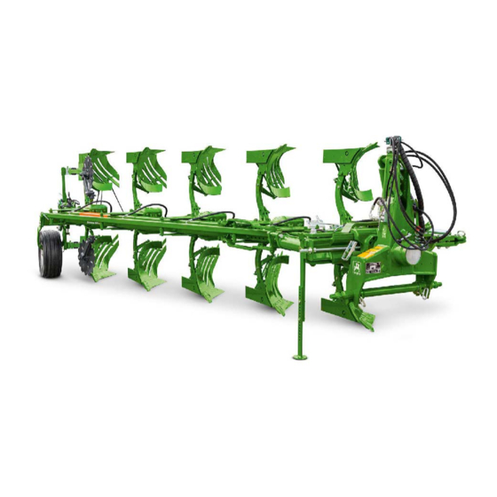
Mounted reversible plough
MG5698
BAG0172.7 02.20
Printed in Germany
en
Operating manual
az
Cayros
M
XM
XMS
XS
XS-Pro
Cayros
M V
Cayros
XM V
Cayros
XMS V
Cayros
XS V
Cayros
XS-Pro V
Read and observe this
operating manual before using
the implement for the first time!
Keep it in a safe place for future
use!
Advertisement
Table of Contents

Subscribe to Our Youtube Channel
Related Manuals for Amazone Cayros Series


Summary of Contents for Amazone Cayros Series
- Page 1 Operating manual Cayros Cayros Cayros Cayros Cayros XM V Cayros Cayros XMS V Cayros Cayros XS V Cayros XS-Pro Cayros XS-Pro V Mounted reversible plough Read and observe this operating manual before using MG5698 the implement for the first time! BAG0172.7 02.20 Keep it in a safe place for future Printed in Germany...
- Page 2 READING INSTRUCTION manual and to adhere to it should not appear to be inconvenient and superfluous as it is not enough to hear from others and to realise that a implement is good, to buy it and to believe that now everything would work by itself.
- Page 3 + 36 (06) 20/469 6360 Fax: + 36 (06) 696/576-662 Spare part orders Spare parts lists are freely accessible in the spare parts portal at www.amazone.de. Please send orders to your AMAZONE dealer. Formalities of the operating manual Document number: MG5698 Compilation date: 02.20 ...
- Page 4 We update our operating manuals regularly. Your suggestions for improvement help us to create ever more user-friendly operating manuals. AMAZONEN-WERKE H. DREYER GmbH & Co. KG Postfach 51 D-49202 Hasbergen, Germany Tel.: + 49 (0) 5405 50 1-0 E-mail: amazone@amazone.de Cayros BAG0172.7 02.20...
-
Page 5: Table Of Contents
Table of Contents Implement description ................. 7 Rating plate ..........................7 Proper use..........................7 Safety first ....................8 Safety instructions ........................8 Safety and accident prevention regulations ................9 Warning symbols and other labels on the implement ............11 2.3.1 Positions of warning symbols and other labels .............. - Page 6 Table of Contents Lighting - Warning equipment for road transport ..............48 Overload safety device ................49 List of shear bolts ........................49 Shear bolt ..........................49 SEMI-automatic ........................50 Automatic hydraulic stone release ..................51 9.4.1 Hydraulic stone release with central pressure setting ............52 9.4.2 Hydraulic stone release with decentralised pressure setting ..........
-
Page 7: Implement Description
The customer acknowledges that the implement may not be intended for use on public roads and may not have the safety equipment required for road traffic. AMAZONE Technology Kft. points out that the vehicle owner as well as the... -
Page 8: Safety First
Table of Contents Safety first Safety instructions It is imperative that the following instructions be observed: 1. When uncoupling plough from tractor, ensure that the stand support is properly clamped! 2. Road transport with transport swing support wheel: When transporting on public roads, road traffic regulations must be observed! On transport journeys with transport swing support wheel, the tractor's toplink must be dismounted. -
Page 9: Safety And Accident Prevention Regulations
Safety first Safety and accident prevention regulations 1. Operators shall wear close-fitting clothing. Solid footwear must be worn. 2. Special care is to be taken when handling any sharp and pointed tools and components - Risk of injury! 3. Before initial operation, please familiarize yourself with all equipment and operating elements as well as their function - both on the tractor and on the plough! It is too late to do this during working operation. - Page 10 Table of Contents 23. If using subsoilers, the subsoiler(s) must be dismounted on the release side and removed to ensure the stability of the plough. 24. Make sure that no people or animals are within the working and swivelling range of the plough. The implement operator is responsible for people and animals in work area.
-
Page 11: Warning Symbols And Other Labels On The Implement
Safety first Warning symbols and other labels on the implement Always keep all the warning symbols of the implement clean and in a legible state. Replace illegible warning symbols. You can obtain the warning symbols from your dealer using the order number (e.g. MD 075). -
Page 12: Positions Of Warning Symbols And Other Labels
Table of Contents 2.3.1 Positions of warning symbols and other labels Warning symbols The following diagrams show the arrangement of the warning symbols on the implement. Cayros BAG0172.7 02.20... - Page 13 Safety first Order number and explanation Warning symbols MD 078 Risk of crushing of fingers/hand by accessible, moving parts of the implement! This hazard can cause the most severe injuries with loss of body parts. Never reach into the hazardous area while the engine of the tractor with connected universal joint shaft/hydraulics/electronic system is running.
- Page 14 Table of Contents MD 096 Danger from escaping high-pressure hydraulic fluid due to leaking hydraulic hose lines. This danger may cause serious injuries, perhaps even resulting in death, if escaping high-pressure hydraulic fluid passes through the skin and into the body. •...
- Page 15 Safety first MD 114 This pictogram indicates a lubrication point. MD 199 The maximum operating pressure of the hydraulic system is 210 bar. MD240 Remove the upper link from the mounting body for transport and secure the implement. MD241 The coupling point of the upper link on the implement side must be located at the front in the slot of the support frame.
-
Page 16: Model Overview / Technical Data
Table of Contents Model overview / Technical data Overview of the equipment versions MODEL XSPro Medium Medium Medium For large tractors series for weight model weight universal use series, premium universal use class, specially for maize straw, up to 105 cm to 120 to 140 to 175... - Page 17 Model overview / Technical data Equipment versions for mounted reversible plough Additional equipment: Disc coulter: For clean furrow clearing • Landside coulter: More inexpensive version instead of the disc • coulter; mounted on the plough head Fertiliser skimmer: Universal use, from ploughing up grassland •...
-
Page 18: Technical Data
Table of Contents Technical data 3.2.1 Ploughs with mechanical cutting width adjustment kW/HP* Share Type Interbody Cutting width Underbe Clear span max. HP Weights (kg) clearance. (mm) range (cm) clearand (PS)- Cayros e (cm) M 850 S 32/36/40/44 1150 - 1700 88 (120) 1105 –... -
Page 19: Ploughs With Infinitely Variable Hydraulic Cutting Width Adjustment
Model overview / Technical data 3.2.2 Ploughs with infinitely variable hydraulic cutting width adjustment kW/PS* Shares Type Interbody Cutting width Underbe Clear span max. HP Weights (kg) clearance. (mm) range (PS)- (cm) clearande Cayros V (cm) M 950 V 32 - 52 950 - 1500 88 (120) –... -
Page 20: Preparations On The Tractor And Plough
Table of Contents Preparations on the tractor and plough Calculating the actual values for the total tractor weight, tractor axle loads and load capacities, as well as the minimum ballast The approved total tractor weight specified in the vehicle documentation must be greater than the sum of the empty tractor weight •... -
Page 21: Data Required For The Calculation
Preparations on the tractor and plough 4.1.1 Data required for the calculation Fig. 1 [kg] Empty tractor weight See tractor operating manual or vehicle [kg] Front axle load of the empty tractor documentation [kg] Rear axle load of the empty tractor [kg] Total weight rear mounted implement or rear Please see technical rear mounted... -
Page 22: Calculation Of The Actual Total Weight Of The Tractor/ Implement Combination
Table of Contents 4.1.2 Calculation of the required minimum front ballast G of the tractor to V min ensure safe steering • − • • • Enter the numeric value for the calculated minimum ballast G V min required on the front side of the tractor, in the table (section 4.1.7). 4.1.3 Calculation of the actual tractor front axle load T V act... -
Page 23: Table
Preparations on the tractor and plough 4.1.7 Table Actual value according to Approved value Double approved calculation according to tractor load capacity (two instruction manual tyres) Minimum ballast front/rear Total weight ≤ Front axle load ≤ ≤ Rear axle load ≤... -
Page 24: Preparation On The Tractor
Table of Contents Preparation on the tractor • Familiarize yourself with all functions on the tractor!! • Read the operating manual of the tractor manufacturer! Tyres: Tyre pressure, especially that of the tractor's rear wheels, must be identical. Ballast weights: Ensure adequate front ballasting of your tractor. -
Page 25: Preparation On The Plough
Preparations on the tractor and plough Preparation on the plough Lubrication: Protective varnish: Lubrication plan Grease all of the Strip the protective varnish lubrication points (see from the shares and lubrication schedule)! mouldboards. A- G Lubrication points must be lubricated regularly with a grease gun (grease nipple). -
Page 26: Mounting And Dismounting The Plough
Table of Contents Mounting and dismounting the plough As a rule: • The plough may only be mounted on the tractor's lifting gear using original parts with matching connection size (Category 2 or • Before mounting or dismounting the plough on the tractor's lifting gear, move the control lever for the hydraulic system to a position where unintentional lifting or lowering of the three-point linkage is ruled out. -
Page 27: Mounting The Plough
Mounting and dismounting the plough Mounting the plough Stand the plough in working position and connect to tractor as follows: For models with four-share design and above, the mounting axle • diameter must have a pin diameter of 36 mm or ball diameter of 64 mm. -
Page 28: Hydraulic Connections
Table of Contents Hydraulic connections All hydraulic hose lines are equipped with grips. • Coloured markings with a code number or code letter have been applied to the gripping sections in order to assign the respective hydraulic function to the pressure line of a tractor control unit! Films are stuck on the implement for the markings that illustrate the respective hydraulic function. -
Page 29: Coupling The Hydraulic Hose Lines
Mounting and dismounting the plough WARNING Danger of infection from escaping hydraulic fluid at high pressure! When coupling and uncoupling the hydraulic hose lines, ensure that the hydraulic system is depressurised on both the implement and tractor sides. If you are injured by hydraulic fluid, contact a doctor immediately. 5.3.1 Coupling the hydraulic hose lines WARNING... -
Page 30: Turning The Plough
Table of Contents Turning the plough As a rule: All (hydraulically) actuated • components have shear and crush points. Maintain a safe distance! • Direct persons out of the • danger area! CAUTION Before each turning • procedure, make sure that THE PLOUGH SWEEPS OUT nobody is standing in the WHEN IT IS TURNED! -
Page 31: Turning With Double-Acting Automatic Cylinder
Turning the plough Turning with double-acting automatic cylinder The double-acting automatic cylinder is equipped with automatic reversing and hydraulic end position locking. This requires double-acting control unit on the tractor. The double-acting automatic cylinder can also be connected to a single-acting control unit, but this requires an oil return line to the oil tank of the tractor. -
Page 32: Turning With Double-Acting Automatic Cylinder In Conjunction With Hydraulic Beam Pivoting
Table of Contents Connection to a single-acting control unit with oil return line to the tractor tank The switching process for turning is the same as with connection to a double-acting control unit, but reverse turning in position is not possible! Turning with double-acting automatic cylinder in conjunction with hydraulic beam pivoting The beam pivoting cylinder is combined with the turning cylinder. -
Page 33: Adjusting The Plough
Adjusting the plough Adjusting the plough General When using the plough for the first time, it is recommended that the diverse rough adjustments be carried out in the yard. If these adjustment recommendations are followed, it is generally only necessary to make small correcting adjustments on the field. The adjustments are made with the plough mounted on the tractor! Top link Connect upper connecting rod to plough... -
Page 34: Mechanical Cutting Width Adjustment
Table of Contents Mechanical cutting width adjustment Cutting width 32 – 44 cm for M850, XM-, XMS-, XS- and XSPro 850 Cutting width 36 - 48 cm for M 950, 1020, XM-, XMS-, XS-, XSPro950, -1050 and -1150 1. Loosen the front plough beam bolt (item 1). 2. -
Page 35: Infinitely Variable Hydraulic Cutting Width Adjustment
Adjusting the plough Infinitely variable hydraulic cutting width adjustment The infinitely variable cutting width adjustment is performed using the double-acting tractor control unit. The scale displays the set cutting width. Infinitely variable cutting width adjustment is possible in a range between 32 and 52 cm (for VARIO 850) and 35 –... -
Page 36: Front Furrow Width - Rough Adjustment Of The Plough On The Tractor
Table of Contents Front furrow width - Rough adjustment of the plough on the tractor Depending on the different clear spans of the tractor wheels and the set cutting width S, the plough is first roughly adjusted carried out using the slide block guide by means of the width adjustment spindle V. -
Page 37: Working Depth Adjustment
Adjusting the plough Working depth adjustment Increase: Set the control hydraulics to greater depth, shorten top link, raise the support wheel(s). Decrease: Set the control hydraulics to a smaller depth, lengthen top link, lower the support wheel(s). Depth adjustment using the control hydraulics, see operating manual from the tractor manufacturer. -
Page 38: Pitch Adjustment
Table of Contents Pitch adjustment The pitch is set using adjusting spindles (1) on left and right separately, so that plough legs or beams (2) are at right angles to the ground. To turn adjusting spindles, briefly place turning cylinder under pressure. Cayros BAG0172.7 02.20... -
Page 39: Pulling Point Setting
Adjusting the plough Pulling point setting The plough should generally be set so that there is no lateral pull on the tractor. Put lower lift arms in correct positon to avoid lateral pull. For normal usage the plough is set so that mounting body (A) runs centrally to the tractor tracks. -
Page 40: Precise Front Furrow Adjustment
Table of Contents Precise front furrow adjustment For precise front furrow adjustment on the field, observe the following: Make the adjustments at a standstill. • • Relieve the slide block guide using the tractor rear hydraulic system. To do so, lift the plough out of the furrow and put it back down lightly, so that the slide block guide is relieved as much as possible. -
Page 41: Disc Coulter Adjustment
Adjusting the plough Disc coulter adjustment 7.8.1 Disc coulter adjustment for standard After loosening the bolt and adjusting the swing arm A, the depth of the disc coulter is adjusted for the desired work depth so that the hub does not touch the ground. When adjusting swing arm (A), make sure that the toothed serrations slots together smoothly and that screw (S) is securely tightened. -
Page 42: Disc Coulter Adjustment For Vario
Table of Contents 7.8.2 Disc coulter adjustment for Vario Only adjust the disc coulter in the direction of travel with the largest possible cutting width! After loosening the bolt and adjusting the swing arm S, the depth of the disc coulter is adjusted for the desired work depth so that the hub does not touch the ground. -
Page 43: Disc Coulter Adjustment For Automatic Stone Release
Adjusting the plough 7.8.3 Disc coulter adjustment for automatic stone release After loosening bolt and adjusting the rocker bar A, the depth of the disc coulter is adjusted for the desired work depth so that the hub does not touch the ground. When adjusting rocker bar A, make sure that the cogs engage smoothly and that bolt is securely tightened. -
Page 44: Fertiliser Skimmer
Table of Contents Fertiliser skimmer The fertiliser skimmers must be set so that the working depth is approximately 1/3 of the plough body working depth. For large crop residues, it can also be set somewhat deeper. Should the fertiliser skimmers be obstructed by oversized crop remains, they can easily be removed by loosening 3 screws. -
Page 45: Swivel Arm For Supporting A Packer
Adjusting the plough 7.10 Swivel arm for supporting a packer (1) Working width adjustment Position the swivel arm with pins in a suitable hole in the hole group and secure with a linch pin. Transport: Set the smallest working width. (2) Pegging position for pins in working position. -
Page 46: Road Transport
Table of Contents Road transport WARNING Cayros V Danger during transport due to unintentional swivelling out of the machine or machine parts! Observe the maximum transport width. Before road transport, move the plough into transport position. Procedure for ploughs with transport pendulum support wheel: 1. -
Page 47: Rear Transport Pendulum Support Wheel
Road transport Rear transport pendulum support wheel Version Ø One stalk = Standard 550,600,680 Double stalk = Heavy 600.680 Move the transport swing support wheel into transport position: Detach the hydraulic damper from the • support wheel stalk (remove split-pin), fold it up and position it between the lugs using the linch pin. -
Page 48: Lighting - Warning Equipment For Road Transport
The customer acknowledges that the implement may not be intended for use on public roads and may not have the safety equipment required for road traffic. AMAZONE Technology Kft. points out that the vehicle owner as well as the... -
Page 49: Overload Safety Device
Overload safety device Overload safety device List of shear bolts Plough Hexagonal bolt as a shear bolt Cayros XS M16 x 72 10.9 Cayros XS Pro M16 x 80 10.9 Cayros XMS M16 x 65 10.9 Cayros XM M16 x 65 10.9 Automatic stone release M16 x 65 10.9 Shear bolt... -
Page 50: Semi-Automatic
Table of Contents SEMI-automatic The semi-automatic stone release is used when there are so many stones in the soil that the shear bolt safety would react too often. The semi-automatic stone release functions as follows: When the plough body meets an obstacle (stone), roller pins (item 1) and bearing rollers (item 2) activate the catches (item 3) and thus compress the compression springs (item 4). -
Page 51: Automatic Hydraulic Stone Release
Overload safety device Automatic hydraulic stone release When the plough body meets an obstacle (stone), the plough beam element turns upwards through the ball joint. When the obstacle has been passed, the plough beam element falls back into original position. The whole procedure occurs without having to stop the tractor. -
Page 52: Hydraulic Stone Release With Central Pressure Setting
Table of Contents Pressure on the hydraulic accumulator: Pre-tensioning 90 bar The gas pressure side may only be set by the pressure dealer and must be checked once annually! (nitrogen) Min. working pressure 90 bar (hydr. oil) Max. working The maximum pressure set must not pressure 140 bar exceed 140 bar, otherwise... -
Page 53: Hydraulic Stone Release With Decentralised Pressure Setting
Overload safety device 9.4.2 Hydraulic stone release with decentralised pressure setting Before operation, the tripping pressure can be set independently for each share. For setting the pressure, use the intended pressure control hose with pressure gauge. Setting the tripping pressure 1. -
Page 54: Cleaning, Maintenance And Repair
Regular and proper maintenance is a requirement of our warranty conditions. • Use only genuine AMAZONE spare parts (see "Spare and wear parts and aids" section. • Use only genuine AMAZONE replacement hoses, and hose clamps made of V2A for assembly. - Page 55 Cleaning, maintenance and repair Observe legal requirements when disposing of lubricants, e.g. • oils and grease. Also affected by these legal requirements are parts that come into contact with these lubricants. Do not exceed a greasing pressure of 400 bar when greasing •...
-
Page 56: Cleaning
Table of Contents 10.1 Cleaning The implement must not be cleaned with a steam jet cleaner • within the first 3 months! After this time, only clean at a nozzle distance of at least 50 cm at 100 bar and 50°C! When the cleaning and care instructions are not observed, any •... -
Page 57: Storage / Overwintering
Cleaning, maintenance and repair 10.2 Storage / overwintering After use, clean the implement with a normal water jet (oiled • implements should only be cleaned on washing sites with oil separators). Dirt attracts moisture and leads to the formation of rust. •... -
Page 58: Maintenance Schedule - Overview
Table of Contents 10.3 Maintenance schedule – overview Execute maintenance tasks after the first scheduled • maintenance period has been reached. The times, running hours or maintenance intervals of any • third party documentation shall have priority. Before each start-up 1. -
Page 59: Checking The Condition Of The Shares And Wear Parts
Cleaning, maintenance and repair 10.4 Checking the condition of the shares and wear parts Replace worn shares and mould boards promptly to prevent damage to the frogs or supporting parts. The same applies to leading tools, if equipped 10.5 Checking the shear bolts Check the bolts for tightness. -
Page 60: Checking The Support Wheel
Table of Contents 10.6 Checking the support wheel Regularly check • that wheel nuts are firmly seated. ο tyre inflation pressure. ο Support wheel Required tightening torque for Required tyre inflation pressure diameter Ø wheel nuts / bolts 5.0 bar 3.6 bar 150 Nm Single shaft... -
Page 61: Hydraulic System
Cleaning, maintenance and repair 10.7 Hydraulic system WARNING Risk of infection through the high pressure hydraulic fluid of the hydraulic system entering the body. Only a specialist workshop may carry out work on the hydraulic • system. • Depressurise the hydraulic system before carrying out work on the hydraulic system. -
Page 62: Labelling Hydraulic Hose Lines
Replace the hydraulic hose line if it is damaged or worn. Only • use genuine AMAZONE hydraulic hose lines. The hydraulic hose lines should not be used for longer than six • years. This period includes any storage time of a maximum of two years. -
Page 63: Maintenance Intervals
Cleaning, maintenance and repair 10.7.2 Maintenance intervals After the first 10 operating hours, and then every 50 operating hours 1. Check all the components of the hydraulic system for tightness. 2. If necessary, tighten screw unions. Before each start-up: 1. Check the hydraulic hose lines for visible damage. 2. -
Page 64: Installation And Removal Of Hydraulic Hose Lines
Table of Contents 10.7.4 Installation and removal of hydraulic hose lines • only genuine AMAZONE replacement hoses. These hoses stand up to chemical, mechanical and thermal loads. hose clips made from V2A for fitting hoses, as a rule. • When installing and removing hydraulic hose lines, always observe the following information: •... -
Page 65: Screw Tightening Torques
Cleaning, maintenance and repair 10.8 Screw tightening torques 10.9 12.9 M 8x1 M 10 16 (17) M 10x1 M 12 18 (19) M 12x1,5 M 14 M 14x1,5 M 16 M 16x1,5 M 18 M 18x1,5 M 20 M 20x1,5 M 22 M 22x1,5 1050... -
Page 66: Malfunctions And Their Correction
Table of Contents Malfunctions and their correction Plough does not penetrate Draw transverse furrows at the ends of the field • into the soil: Shorten the top link • Replace the shares or use chisel shares • Set the disc coulter and fertiliser skimmer higher up •... - Page 67 Malfunctions and their correction Cayros BAG0172.7 02.20...
Need help?
Do you have a question about the Cayros Series and is the answer not in the manual?
Questions and answers