Table of Contents
Advertisement
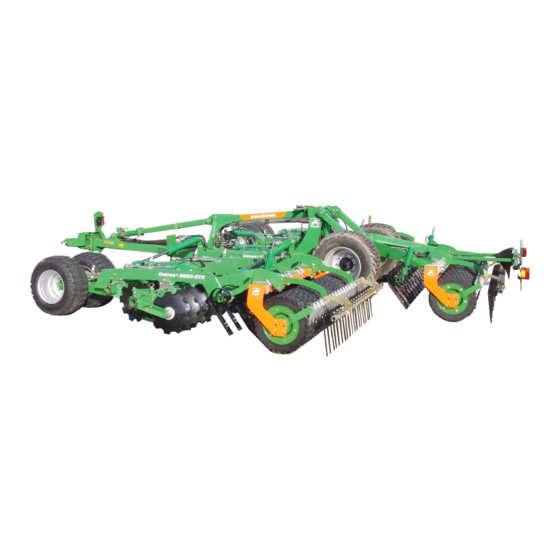
Catros 7003-2TX
Catros 8003-2TX
Catros 9003-2TX
MG5527
BAG0159.8 02.20
Printed in Germany
en
Operating Manual
az
Mounted compact disc harrow
+
Catros
7003-2TX
+
Catros
8003-2TX
+
Catros
9003-2TX
Please read and follow this
operating manual before putting
the machine into operation.
Keep it in a safe place for
future use.
Advertisement
Table of Contents


Need help?
Do you have a question about the Catros 7003-2TX and is the answer not in the manual?
Questions and answers